TED6000 Pro replacement

Hello all, I have been using a TED6000 pro with a Spyder at home for more than 3 years. A few months ago the base station gave up and I don’t feel like replacing it. Still I have the MTU and the Spyder in working order, I don’t know if I can do something with them or reuse them with emonCMS (don’t think so).

Now I would like to reuse the existing CT clamps. So I installed EmonCMS on a raspberry Pi 3B+ and plugged it on my network. I then programmed a Wemos D1 mini with a CT clamp (SCT013. 30A → emon1.current(ADC_INPUT, 70);). It works well and post data to the EmonCMS. Next step, I bought a ESP-WROOM-32D ESP32-DevKitC who has 12 analog pins(I need 10 Analogs). I should receive it this week. The TED Spyder has 8x60A small CT clamps(CT003A) on individual brakers And the TED MTU 2x200A on the main (one on each main wire).

So here come the questions:

  • How can I ensure I have very accurate readings ? I used kill a watt to calibrate my ct clamp, but the calibration(70) is not always spot on. How can I properly calibrate ? tutorial? I used a 43R as charge, I don’t have 33R on hand :frowning:

  • For the 2 ct clamps(200A) on the main, is there a tutorial for these, all tutorials deal with a single clamp, how can I properly measure the 2 ct clamps on the mains? Should I use the same resistors ? (10K-10K-33R)

  • I have a ACS712 Arduino sensor, can I use it to measure the voltage and get better readings ? I was planning on building something to power the ESP32 from a breaker(without CT) with an adaptor and also measure the voltage on this breaker, but, can I use this to calculate the Kw on other breakers ?? Will it be accurate?

I still lack a lot of knowledge, I’m a begginer, so I need more guidance please.
Thanks a lot!
Welcome, Drake, to the OEM forum.

This sounds like a very big job. I’m not familiar with most of the items you mention, but I can address a few general points.

Usually, that requires very accurate (hence expensive) test gear. Every electrical and electronic part ever made is subject to manufacturing tolerances, and it’s these that mean that, for the best accuracy, everything must be individually calibrated (that means not just the current transformer, but the combination of current transformer, burden resistor and everything else associated with that input).
(That’s why your TED stuff quotes ± 5% - they can’t promise closer because of all those tolerances adding up.)

The procedure for our emonTx is spelled out step-by-step in the ‘Learn’ section here, along with a lot of (hopefully) useful background information. The details for your kit will be different - the general procedure will however apply.

You really should use the correct burden for the job in hand. A current transformer is happiest when it’s working into the lowest possible resistance (that’s minimum load), but that must be balanced against the input voltage requirements of whatever is measuring the voltage. You need to know or measure the characteristics of the current transformer - its current ratio, maximum rated current and VA rating, and the requirements of your (say) ESP32, to determine the burden value you need.

If they each have their own input, you don’t - you treat them individually. If they’re connected in parallel, then remember that a c.t. is a current source, so you treat them as one c.t. that delivers twice the current as each does on its own, and calculate the burden from that. If they each have their own burden, they become voltage sources and you wire them in series (See our “Use in N.America” page for more details) and each contributes half the total voltage.

NO
The ACS712 is a current sensor - there will be a flash and a bang if you connect it to measure voltage, and something will get damaged. Make sure it’s not you.

There should be little inaccuracy if you use the same voltages everywhere - experience tells us that generally, there’s no need to measure both legs of your supply, because the voltages are reasonably well balanced. But you might gain a little if you do measure both and use one, or the other, or the sum as appropriate to the circuit you’re interested in.

you could if you want see if your MTU will work with this

1 Like

Well, thanks to stephen I’m on a completely new track. I’m trying to connect my ted6000 mtu to emoncms using a wemos d1 as interface. Currently I found the Rx and Tx on the mtu and connected to the wemos serial port. I receive the communication so now I’m trying to decipher everything, but stephen already did most of the heavy work so it’s going well. The ted5000 send 11 bytes of data, the ted6000 seems to send 31 bytes, so stephen decoding doesn’t work :frowning:

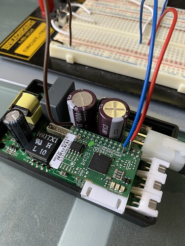
Below a photo for those wishing to do the same. The brown wire is the common ground, the red wire must go directly into the wemos RX pin.

I discovered that if your ecc is dead the ted6000 mtu needs a request paquet to initiate communications. I connected the blue wire to D4 on my wemos and used serial1 to send AA as request. It seems to work.

1 Like