Hello. I found this post while looking for a voltage/current logger using my Pi4. I am curious how did this project turn out and if I can learn more about it to make it work with my battery.
I have a basic battery monitor (coulomb counter) that uses 350A rated shunt. I also have Pi4 onboard for SignalK and N2K, etc. Would like to read low-side shunt and input into Pi4 via I2C interface. It looks like the adafruit little board could do that but I am really confused about the amperage limitations. In theory I could be having as much as ~100A going through the shunt. Would it fry the INA260 board?
I got sidetracked a bit on other measurements since I started this chain. Subscribe to it and I will update as I get around to my power measurements. I’ve been more focused on getting signals from all over the boat to my ESP32’s. The physical connections/wiring are always a challenge on a boat as I am sure you know from your own experience.
Tim
If you put an INA260 in parallel with your shunt, you are putting 2 mΩ in parallel with whatever the resistance of your shunt is, so the current will share in inverse proportion to the resistances (remember to include any connector contact resistance in the calculation). If your 350 A shunt is a standard 75 mV one (150 mV is also a common standard), the resistance is 0.214 mΩ, so very roughly, 35 A will flow in the INA260 and 350 A in the shunt. So, you cannot do that.
You would need to add more resistance in series with your INA260, which would need to be calibrated. And ideally of course, you should use a metal with a low temperature coefficient of resistance.
Actually the shunt is 500A (as I wrote in another post you kindly replied to. Sorry for the mixup).
Thats a bummer I would not be able to use this INA260 without adding additional resistance. I dont have any calibration equipment that can reliably determine exact Ohm value. The other day I bought 8 wire wound 4Ohm resistors and they all came with a range of 4.6-4.9Ohms or 19% (nineteen) deviation. I was able to get these values from my inexpensive digital multimeter but I would not trust it for milliohms resolution.
The problem you have with measuring d.c. is isolation. With a shunt, you must take steps to make sure that the voltage you are measuring across the shunt does not interfere with, or is not itself interfered with by the voltage that supplies the instrument.
The ACS770 range goes up to ±200 A, it is a Hall effect device so provides the necessary isolation between the supply and the circuit being measured, runs off 5 V and will give you a 5 V output swing (2.5 V ± 2.5 V). That will interface directly to a 5 V Arduino, for example.
Thank you for your continued patience with me as I clearly show lack of any knowledge on this. The part I an not fully understanding is that I am measuring millivolts across the shunt. The shunt itself is rated to handle high amperage but the measurement instrument (volt meter or INA breakout board) only needs to be precise enough to accurately detect millivolts. Is that correct?
For example, given my existing shunt known R value of 0.15 milliohms if I am passing a hypothetical 80A load then the voltage drop would equal to 12mV (R * I = V) .
If I got this correctly, using this example above to do this in reverse I need:
a) voltage between + and - of the terminal 1 on the shunt.
b) voltage between + and - of the terminal 2 on the shunt.
c) subtract values A-B to get the mV value of the voltage drop. (V)
d) V / R = I or 0.012 / 0.00015 = 80A
I’m not sure what you’re doing there, but I think you’ve got a bit mixed up.
First, don’t think about the shunt resistance when you’re using it as it is intended. It is intended to convert a current into a voltage - in your case 75 mV given 500 A. All you’re interested in is the voltage between the (inner) instrument terminals. That’s what it’s calibrated for. You don’t know, and you don’t care, what the voltage is between the heavy current terminals.
So very simply, your voltage at 80 A = 75 mV × 80 ÷ 500. It still comes to 12 mV, but surely it’s easier to remember that way?
(And you’ll never find a shunt resistance published - they are always given as a current and a voltage.)
@Robert.Wall I’ve been reading and found at least part of my missing knowledge. I’ve learned today the difference between ammeters and galvanometers. So now, armed with this knowledge, I know that I am not trying to build an ammeter that is connected in series with my load. Instead I am trying to build essentially a galvanometer which is connected in parallel with the load via shunt and measure milli or micro Amps.
I’ve yet to find the appropriate breakout board for this task but at least now I know what I am looking for.
You could go either way: add something like the ACS770 in series with your shunt and the load; or measure the few millivolts available from your shunt. I think the former would in fact be easier, but you have the not insignificant problem of mounting the ACS770 and handling the not insignificant current.
If you favour the latter, then - assuming you want a digital output from an ADC, you’ve got to use an ADC (or precede it with an amplifier) that will handle not only the very small input voltage, but you also have the problem that this voltage might be outside the supply voltages for your ADC, and I don’t know offhand of an ADC that will do that. It could prove a very difficult problem to solve.
Forgive me but why digital ammeters with a shunt can be bought so cheaply everywhere? Within $20 will give amp and volt reading off of a shunt. All I am doing is replacing the useless LED screen with sending the values to arduino. I must be missing the complexity Im facing.
I think that’s it. When you have a self-contained instrument, the manufacturer has compete control over what happens inside, and doesn’t need to worry about connections to the outside world.
You are making connections to the outside world, therefore you need to take on all the problems that can arise from that.
That’s why I suggested the ACS770 series of transducer. You connect the main terminals in series with the battery and shunt. There’s no galvanic connection between that and the electronics, the connection is the magnetic field around the conductor that carries your 60 A (or whatever it is), so you don’t need to worry about putting a wrong voltage into the ADC input. You connect the sensing side to your Arduino (getting the 5 V supply from that) and power the ACS770 & Arduino however is appropriate, write a sketch to scale the numbers and send them to your Pi via a serial connection to one of the GPIO pins, exactly as we do with the emonTx and the emonPi.
Digikey do a range of demo boards with the sensor already mounted.
Hi Val,
I have been following along on these posts. very interesting and helpful.
I’ve also taken a look at the Victron Smart Shunt as a possibility. Not the cheapest solution (~$130US) but seems to give a tremendous amount of information and in the end, given all the seeming nuances associated with a discrete component solution, might be a better approach in the long run. I believe there are other vendors of similar products.
Yes, I’ve been looking at this Victron shunt as well. $130 is not a huge amount of money considering boat units. I was really enjoying making my meter. Still I might get the Victron later on. With that said, I was able to achieve what I was hoping for. Here is what I’ve done:
Generic INA219. Removed onboard R100 resistor.
Connected the leads to my shunt.
Downloaded and slightly modified this library https://github.com/flav1972/ArduinoINA219
so far I’ve tested it with upto 22amp load and it has been very accurate.
it also reports on the voltage which again is very accurate.
Below is the arduino code but I plan to transition it to Pi4 so to keep all in one. Ultimate goal is for the SignalK to display the data. Now that I have the data I am trusting, im considering doing nRF24.
One has to pay attention to the shunt configurations. The larger the range the less accurate results will be. In my case I purposely limited shunt values to 40amp.
Another note is the ShuntCurrent multiplication. the sensor is reading tinny current from the shunt which has to be multiplied to receive real amps being drawn. I arrive at this number by trial and comparison against my multimeter and data from the battery BMS.
#include <Wire.h>
#include <INA219.h>

#define SHUNT_MAX_V 0.006 //rating for max of 40amp based on 500A/75mV - (75mV / 1000 = Volts) * 40AMP / 500AMP
                          /* Rated max for our shunt is 75mv for 50 A current:
                             we will mesure only up to 20A so max is about (75 / 1000) * 20 / 50*/
#define BUS_MAX_V   16.0  /* with 12v lead acid battery this should be enough*/
#define MAX_CURRENT 50    /* In our case this is enaugh even shunt is capable to 50 A*/
#define SHUNT_R   0.00015   /* Shunt resistor in ohm */

INA219 monitor;

void setup()
{
  Serial.begin(115200);
  monitor.begin();
  // setting up our configuration
  // default values are RANGE_32V, GAIN_8_320MV, ADC_12BIT, ADC_12BIT, CONT_SH_BUS
  //**************The args are: (range, gain, bus_adc, shunt_adc, mode)
  monitor.configure(INA219::RANGE_16V, INA219::GAIN_1_40MV, INA219::ADC_128SAMP , INA219::ADC_128SAMP , INA219::CONT_SH_BUS);

  // calibrate with our values
  monitor.calibrate(SHUNT_R, SHUNT_MAX_V, BUS_MAX_V, MAX_CURRENT);
}

void loop()
{
  Serial.println("******************");

  Serial.print("raw shunt voltage: ");
  Serial.println(monitor.shuntVoltageRaw());

  Serial.print("raw bus voltage:   ");
  Serial.println(monitor.busVoltageRaw());

  Serial.println("--");

  Serial.print("shunt voltage: ");
  Serial.print(monitor.shuntVoltage() * 1000, 4);
  Serial.println(" mV");

  Serial.print("shunt current: ");
  Serial.print(monitor.shuntCurrent() * 21.90, 4);
  Serial.println(" A");

  Serial.print("bus voltage:   ");
  Serial.print(monitor.busVoltage(), 4);
  Serial.println(" V");

  Serial.print("bus power:     ");
  Serial.print(monitor.busPower() * 1000, 4);
  Serial.println(" mW");

  Serial.println(" ");
  Serial.println(" ");

  delay(500);
}
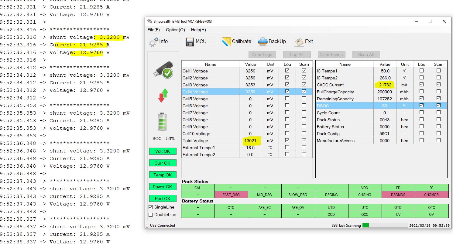
I’ve been doing some high load charge/discharge tests. My discharge load is 7 wirewound resistors in parallel to give me constant and continues load for testing.
Wanted to share screenshot from BMS screen as well as results from INA219 and Arduino.
Shunt/Current/Voltage have all been verified with a digital meter.
Voltage difference between BMS and INA219 is because BMS measures voltage at the battery terminals and INA gets voltage value After BMS. I double checked that this voltage difference is accurate.