Yes interesting it’s on the flow but it does look to be only on the heating side after the 3 port so not in play during DHW.
I guess the assumption is that the volumiser might be needed because TRVs are shutting down so the bypass is in case there is too much restriction on flow. But really TRVs should just be limiting a few radiators in rooms that overheat and I think most pumps can handle this.
I am very open to further more knowledgeable opinion, but I would prefer not to include any additional devices although recognising that the Auto Bypass Valve will probably act as a non return.
Having looked again at my layout, I propose to put the return from the CH into top right and return to the ASHP to bottom left like the sketch. I look forward to further comment.

Your “required” diagram is exactly how my system is set up. There’s a bypass valve between flow and return visible on the picture as well but this is never open as I run a fully open loop and have set the differential pressure so there is no short circuit there under normal operation. Works very nicely for me.

Looks good, that’s exactly how mine is plumbed in.
I also have a bypass valve which would run between your “To CH” and “From CH” boxes. It is closed in all normal operation and would only function if most radiators were turned off.
I guess the Auto Relief Valve is just a variable pressure relief valve which is set to open if all radiator valves are closed. I have intentionally arranged for a couple of small rads to always be open and my Tado TRV’s are set at 24.5C, so there is little chance of such a valve being required.
I still question where connection is made into return line in Samsung drawing.
Hi @AlgarveASHP,
Yes the ARV is to protect the heat pump from zero flow (should all the TRVs close) when no buffer tank is installed. (It isn’t necessarily installed in the buffer tank case because there is always a free flow path, assuming the strainer doesn’t get blocked). I believe most if not all heat pumps also have a low flow trip, but that’s a “last resort” which requires a manual reset (whereas an ARV will just close when an emitter flow is re-established, without stopping the heat pump).
I produced this sketch as part of a write-up I’m doing about heat pumps. I think it’s consistent with the Samsung/Midsummer drawings, and hope it doesn’t confuse you…

(In this sketch the ARV is marked ABV (automatic bleed valve - the alternative terminology).
Sarah
Nice diagram!
My pump is on the flow.
Still trying to work out what the pros and cons are to fitting the volumiser to the flow or return.
I haven’t ever needed one (yet), but if required, a volumiser on the flow could potentially help dilute the cold water a bit from the defrost cycle, before it gets to the rads/UHF. It could also be used to house a backup heater element if need be.
I suspect that for many installations it doesn’t make much difference. If the water circulation rate is more than ~15lpm, that’s only about 3mins residence time in a 50litre volumiser - not long compared with a typical defrost cycle of 10mins or more. So the whole emitter circuit will cool during defrost, irrespective of volumiser location.
I’m happy to be corrected on this - has anyone actually measured the heat consumed by the heat pump condenser during a typical defrost cycle?
Edit: @glyn.hudson’s post Samsung MIM-C02N S-NET Pro Dongle - #11 by glyn.hudson has some useful data on this last point, and it looks like 5mins is a better estimate of defrost cycle time than the 10mins I suggested above (though I think my point about circuit cool-down still stands).
Yes I dare say size matters for both these purposes, but as yet have no real direct experience/comparison, as fortunately my systems generally have sufficient open volume for defrost and to avoid excessive cycling. Would be good to experiment on some smaller systems etc.
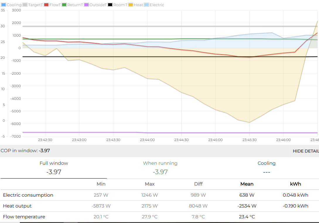
I had a look at it here and found it uses around 1kWh of heat from the house + 0.2 kWh of heat via electricity, so a total of 1.2 kWh in heat (over ~7 minutes for me). 50l of water might be sufficient to provide that energy, say starting from 30 to 15 °C is around 0.9 kWh.
But you’re completely right, the flow rate is what breaks this as the buffer has insufficient volume to provide water for the whole defrost cycle. When the volumizer is in the return path, this will be used to provide the energy for the defrost but the cold water will then directly reenter the radiators. It might be even beneficial to have the buffer in the flow path as the incoming cold water will be mixed with the warm water in the buffer and what enters the radiators is at least somewhat warmed up.
I’m really looking forward to the first really cold days to test out my idea to just close all my TRVs when the defrost starts (can detect this and close them wirelessly), have the automatic bleeder valve open and my 100l volumizer deal with the defrost, only to reopen the TRVs once flow temperature is at a comfortable level.
Then there’s also how it’s piped.
If it’s on the flow and has in at the bottom and out at the top would stratification allow warmer water to be going into the radiators for longer on a defrost?
Or would the turbulence from the introduced water just mix things up fairly quickly?
If it was in at the top and out at the bottom maybe there would be more mixing so a less sudden temperature drop when the volume is used up?
As you would expect, the amount of energy required for defrost is proportional to the size of the heat pump, my 5kW unit seems to require about half the amount of energy to defrost compared to @Andre_K 10kW unit, I’ve observed 0.44kWh being pulled from the emitter circuit and 0.062kWh of electrical power, the defrost lasts approx 7min

I don’t have a buffer or volumiser. I have approx 70L of open-loop system volume in radiators which are always open.

Teaser…
I have partly plumbed up a 50L buffer tank I bought of eBay as a volumiser, stay tuned to this channel to find out the exciting* results on the performance of my system.
*May not be exciting at all and have been a complete waste of my time and many compression fittings
Our 5 kW Arotherm+ with about 150l of open-loop system and 0.048 + 0.19 kWh needed during about 4 min
It’s magic
Well I now have a 50L volumiser in my system.
This is on the flow (to complicated to pipe into the return and couldn’t see that it really mattered apart from higher heat losses).
My system is Emoncms - app view
The extra volume was added to the system yesterday (28/11/2024) from 16:20. Ignore everything earlier in that day as I was messing around with draining the system and then filling up the volumiser. It was lots of ‘fun’ filling it bit by bit while I dealt with the next compression fitting leak!
I’m expecting any improvement to show up tomorrow when things get milder as it shouldn’t make any difference when long running.
However there is a bit of a weird behaviour that has started happening today I’ve not seen as pronounced before:
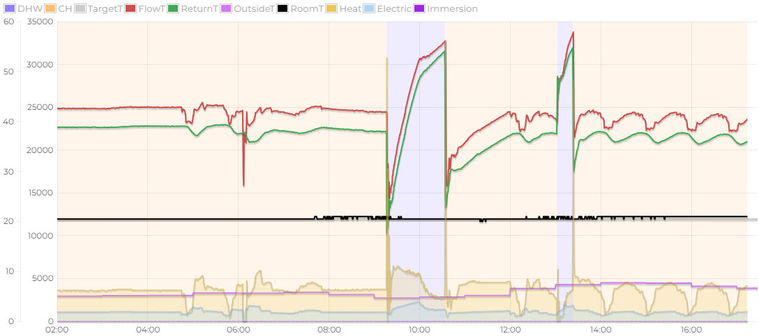
Some weird oscillations have started in the output power as it has warmed up. I run my Ecodan in Auto Adapt mode so maybe it needs to learn the changed behaviour of the system?
@johncantor This behaviour looks like our old friend of strange dips in outout when input power contunues to the compressor?
That is odd… never seen it like that before. I assume the flowrate is contant here? if dt dropping to 1 degree, yes, heat output very low, but how can that be? I’m sure if you went to your FTC screen and Running Information, you would find the discharge temperature very low around the dips. I would expect the problem relates to the exp valve (LEV), or rather, the control telling it what to do. The LEV position is also shown on Running Information, but it may not tell you a lot. I need to have a more detailed look
Yea constant flow rate.
Just gone into a hot water cycle so will be interesting to see what happens after. If it starts oscillating again I’ll see if I can record the discharge temp (004) and super heat (012) running info values.
I caught this dip earlier (Emoncms - app view):
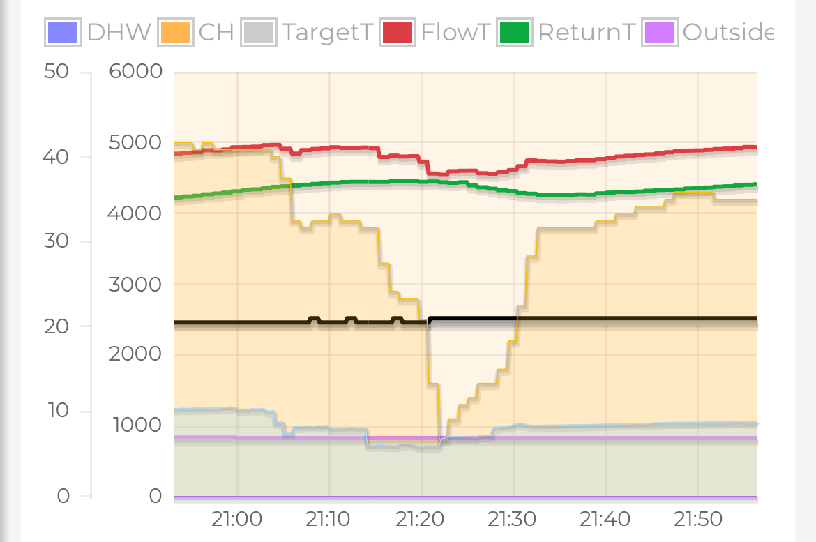
I recorded the discharge temp and superheat:
text.csv (214 Bytes)
But I don’t know if those values are expected or tell us anything about what’s happening.