Hello everyone and thanks for a great community. This is my first post and I’m currently rebuilding a house and installing central heating system with a ASHP and a stove boiler with 20KW of heating capacity.
I plan to install open energy monitor for the system and have created the attached schematic of the system. But I am a bit unsure where to pipe the stove boiler.
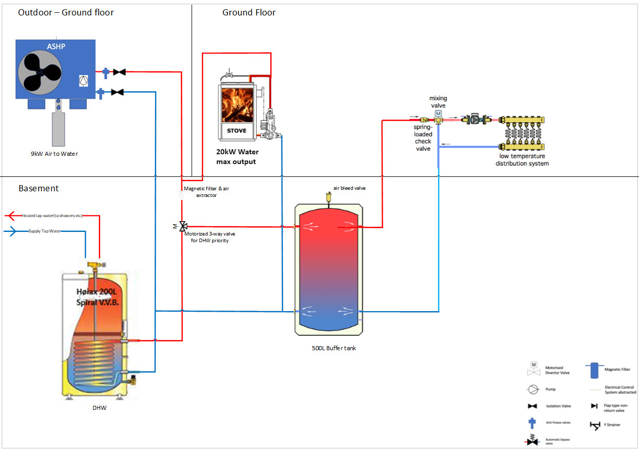
1: Base case per today: Joined with the supply of the ASHP, prior to the 3-way valve
2: Alternative; Directly to the DHW coil and also add the return of the DHW to the buffer tank, before returning back to the wood stove boiler.
3. Add electronic logic, so the 3-way valve can be overridden based on temperature settings, to divert water to DHW or buffertank
Looking forward to getting this system and integrating it with OEM up and running in a few months time!
A warm welcome to the community, Joakim, and sorry that nobody has responded more quickly.
My gut reaction, without getting into equipment details:
I assume your main objective is minimising operating cost. Some ASHPs offer a poor CoP on DHW (because of high exit temperatures if not constrained by the ASHP controller), so if your stove fuel costs are very low, it might be cheaper to heat DHW from the stove, per your alternative option. Or at least pipe this up as the preferred heat source, leaving ASHP DHW as an option in case you don’t want to fire up the stove specially. On the face of it, a second 3-way valve on the stove outlet, routed also to DHW coil, would do the trick. (It would also retain the option to supply everything from the stove, to cover a mechanical failure in the ASHP.)
Incidentally, I’m puzzled by the location of the emitter feed pump. I’d have expected to see it upstream of the mixing valve. What was your logic there?
Thank you for the warm welcome and valuable feedback Sarah, much appreciated!
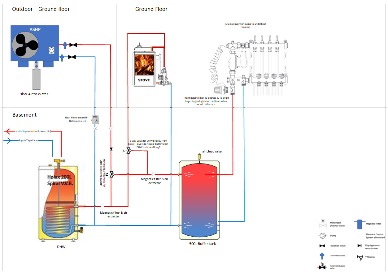
Running cost is the main objective and the stove are primarily used every now and then for the nice atmosphere it adds to the house. Great input and I’ve updated the diagram so it now shows to route the heated water from stove to the DHW, as this high temperature heat will offload the work the ASHP will need to do. This will potentially also reduce the need for the ASHP to execute legionella cycles which further should improve COP efficiency.
I’ve added a second 3-way valve/diverter valve to my diagram. Planning to add a simple logic so that when the DHW tank reach a certain value (ie 85degC) it considerer the DHW fully charged with energy, and logic will operate the 3-way diverter valve so the stove heated water gets routed to the 500L buffer tank.
Excuse my English as its not my main language. But by emitter that’s the circulating pump for the underfloor heating?
I’ve updated the drawing to show a different style mixing/shunt pump group on the drawing. The reasoning by having a mixer/type is tt avoid getting the water circulating to the under floor heating reaching to high of temperatures(my thought process is that this had not been needed if there was no stove in the system).
I’m also running a solar system with 9kWp and 60kWh battery storage. Planning to optimize this and run solar diversion into this system, to maximizing self-conception.
Any further comments, concerns or other input from this fantastic community to further improve the design are much appreciated.
There is absolutely no need for you to apologise, your English is excellent, far better than many people who were born and lived all their lives in England.
No, by “emitter” we mean the device that emits the heat energy - a radiator or your underfloor heating itself.
Excellent response, Joakim, and your English is 100% better than my Norweigan .
Yes, you’ve got the second 3-way valve exactly as I imagined.
Do you really want 85degC DHW?? You will burn yourself! Most folk only need 50degC max (washing up) or even (as I do) just 40degC for showering (my dishwasher/washing machine are cold fill). You will only need 60degC for legionella control once per week or less. The stove would be ideal for this as the ASHP CoP at say 65degC LWT will be very low (LWT = leaving water temperature in case the abbreviation is new to you).
“Emitters” is a collective word for radiators and UFH - anything that consumes the energy your system produces.
Main problem with your design (I’ve just realised) is that you’ll probably need three pumps - one for the ASHP loop, one for the stove loop, and one for the emitter loop (unless you can do something fancy to combine the first two).
I wouldn’t worry too much about high UFH temperature, as long as you can modulate the stove exit temperature (e.g. water flow rate control). If you can aim for something like 40degC ex ASHP and stove that should more than suffice for UFH, and 50degC ought to be enough for DHW (except occasional disinfection).
Will you design the system fully yourself, or will you ask your installer to do this? A good installer will help with heat loss calcs, and specify optimised equipment (e.g. your buffer tank may be oversized/unnecessary - most folk on this forum hate buffer tanks).
Feel free to consult further with the forum as needed - there is lots of experience here, good and not-so-good…
PS I started this reply before Robert posted but was called away, so some overlap.
PPS Very impressive solar system! Your battery is huge by UK standards. Do the Norweigan electricity tariffs justify such a large one? (I thought you had so much hydro that power was almost free… ).
I have similar but the ASHP replaced a large combi gas boiler, so my cunning system of a 500l thermal store heated by either solar thermal/excess PV/wood burner now has a DHW cylinder heated by the ASHP in the mix. But it worked well for the 4 months of the year when needed.
I heat my TS to 95C; why not if you have the free power? The outlet has a mixer set to 45C so nobody gets scalded.
It’s not clear from your diagrams but the wood burner probably needs to be feeding an open vented system unless there is some automatic quenching enabled if power goes off.
Firstly, what’s going to be the primary heat source. If the heat pump was going to be used more than the boiler stove, then I would optimise things for that.
20kW is a big boiler stove, what percentage is to water - a 500L buffer maybe on the small side. Also, if you really want/need something this big and have the space and budget, then maybe consider a proper boiler, like a ETA SH 20kW log boiler and 2000/3000L buffer etc, so much more efficient and less hassle than a boiler stove!
A couple of notes on your proposed layout.
I’m assuming you’re proposing a modern sealed system boiler stove with mains water safety quench coil for over heat protection. If so you will need an appropriately sized primary expansion vessel, which I would connect to the bottom of the buffer tank, or on the return to the boiler stove, between buffer and loading valve set.
I wouldn’t use a diverting valve on boiler stove flow to charge hot water cylinder/buffer. I would connect the boiler stove directly to the buffer. Then run a pipe off the buffer, from top connection, to hot water cylinder coil and use a small pump, controlled via cylinder stat. Use a stat near the top of the buffer to enable/interlock the heat pump. Also, it’s a good idea to control the boiler stove loading valve pump with a flue stat, so that it switches the pump off once the fire is out and not producing heat.
Thanks for all the responses here and your kind comments about my English
This will be a long post, so please bear with me.
I predict that 95+% of the energy needed will be supplied by the ASHP, so this is clearly the primary and main heat source of the system. Backup is a heating element in the tank(in case of heatpump failure). The whole water heating system is new, and I will install the underfloor heating over the weekend together with the plumber. There is an existing fireplace, but this is rarely used as its extremely little inefficiency. We only fire it up a few times a year, as most of the heat escapes out the chimney. A stove/fireplace insert for waterheating has been identified and I like the idea of getting more use and out of fireplace/stove. That being said, I don’t consider it investing in a stove of this type to be financially sensible thing to do, we will never see return of investment on the unit, but at least we will utilize the heat to something so that will give us some satisfaction and give my engineering mentality a peace of mind.
Great input Tony, thanks. I understand 500L Buffer is minimum to the stove. At maximum the stove can produce 20kW energy to the water and 4kW to the air. But normally this is expected to be 1/3 to 2/3 of the max, based on much air is let into the stove. If I could, I have selected a smaller stove, but this is limited my what’s available. Considering adding more buffer in the future but requires large rebuild of the property. Alternatively, the whole stove project gets put on hold, as it has many design implications to the system.
Design updates and comments:
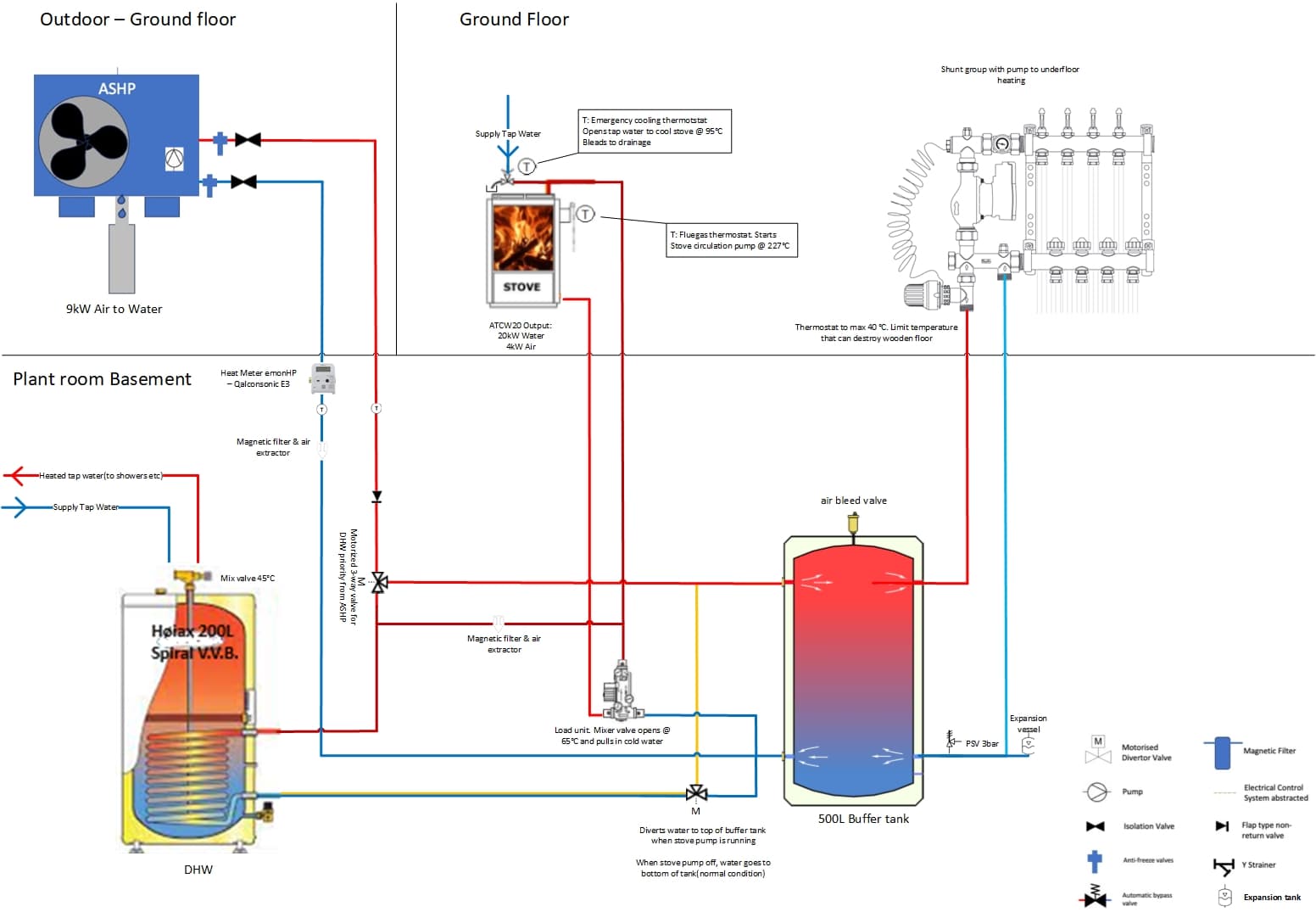
New suggestion: On the diagram I have moved the 3-way valve from LWT stove to directly supply the DHW coil and rather put the 3-way valve on DHW LWT so when the stove circulating pump is running (and injecting heat into the DHW cylinder), it reverts the LWT from the DHW into the top of the buffertank. When the stove is no longer fired and cools off, which again turn off the loading unit circulation pump the 3-way valve goes back to default state with LWT of DHW to divert water to the bottom of the buffer tank. I realize that this will then take longer time to charge the DHW, but the stove has a high kW output(24kw) so I believe this should be ok.
Moved one of the magnet filters to supply the input header of the heatpump. My assumption for this is that the plate heat exchanger and the circulation pump within the ASHP is critical to protect and create ideal running conditions for it. Also, the circulation pump of the ASHP will be running most of the time, thus cleaning the system.
Moved the other magnet filter on the output from the stove. My reasoning is that the stove is the only black steel unit in the circuit, thus creating the most debris into the loop which should be extracted as early as possible.
Added a PSV(Pressure Safety Valve, which bleeds the system pressure if system pressure reaches 1Bar). My understanding is that it does matter where this valve is located as the whole system is connected. Stove maximum water pressure by manufacturer is listed to be 1.25 Bar on datasheet.
Expansion vessel added. I assume that it does not matter where in the system this is connected.
The load unit, which was previously intended to be installed behind the stove, will be installed in the plantroom in the basement. This is to minimize noise from the circulation pump in the living room. This pump starts circulating water when 227°C is reached in the flue gas(Manufacturer specification). The 3-way valve on this will open at 65°C(manufacturer specified to optimize
Added emergency cooling circuit of the stove (directly fed by supply water) Safety valve that opens at 95°C to avoid boiling water in case of a power failure or a pump failure in the load unit
Response to Sarah comment 2: Yes, I aim to have as high temperature as possible in DHW first and then buffer tank. My reasoning with the aim to accumulate as much heat from the stove when it is used. Increasing the Temperature in DHW and buffer up from approx. 40 to 85 degrees in a reservoir of 180L(DHW) 500L(buffer) is approx. 34kWh of stored energy.
Response to Sarah comment 4: Yes, I will need 3 pumps. The ASHP has one built in, the load unit for the stove will need its own to create ideal running conditions for the circuit of the stove and the third pump for emitters. I see no way around these number of pumps. But most of the time only the ASHP and emitter pump for UFH will run.
Response to Sarah comment 5&6: The system delivered by a local supplier that has done heat loss calculation, which is aligned with my own. The aim is to try to have as low circulation temperature as possible, to create as ideal conditions for high SCOP of the heatpump. The plan was to avoid having buffer tank, but as the stove requires a place to dump the heat this became a requirement. Theres a mixing tank on DHW to tap, so can set this to avoid getting to hot water in the tap in the sinks.
I have some neat logic in Solar Assistant(controls battery system and solar inverters) and Home assistant to charge batteries dynamically based on Nordpool electricity prices(extremely variable by hour in Norway). This will further be enhanced to ‘charge’ buffer tank and DHW by ASHP when batteries are full, to minimize export to grid and maximize self-consumption.
Given what you’ve said, maybe consider doing away with the boiler stove and buffer and optimise the system for the heat pump. Keep it simple and efficient, connect it directly to the UFH & DHW cylinder via a 3 port diverting valve, no buffer/low loss header, therefore using just the primary unit pump and no pump or mixer on the UFH. Avoid lots of zoning - just bedrooms and dial in the weather compensation curve to achieve a low flow temperature and avoid switching it on/off. Just make sure it’s correctly sized!
As mentioned, if you wish to use wood to run you’re central heating system, then it’s far better to use a proper gasifying log batch boiler and appropriately sized buffer tank. Simple boiler stoves are inefficient, dirty and a hassle to use, especially big ones with small buffers. Consider a simple small room heating only wood stove as a back-up if need be, which are generally more efficient, cleaner burning and less mess through the house and there’s lots to choose from, just don’t oversize it!
Hi Joakim, @Lakee has given a super reply. All I’d add is that if you do retain 2 parallel pumped heating loops (ASHP + stove), make sure the pumps don’t “fight” each other - if not properly matched, one may stop the other when it cuts in (backpressure mismatch); you don’t want to rely on safety cutouts to protect you.