Or you can supply the 5 V via the FTDI header, or solder a 2-pin header into the holes marked “PWR” - that’s 5 V too.
Oh, nice. I might just use the PWR points.
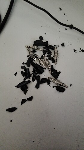
After starting assembling the emonLCD, I found the 3.5mm plugs for the temp sensors and other misc stuff. I think the package sat in a hot container on a ship or in some stock yard for a while… So brittle. lol.
Seeing that, be very careful to test the emonGLCD board before you solder the display itself, because you do not know what other damage has been caused to the other components. It is very, very difficult to work on the pcb after you solder the display in position, and equally difficult to remove it.
Thanks for the tip, I will deffinitely take a good look over the components and verify they look ok, Might even check some with my DMM. That said, the parts /look/ ok at first glance. Cheap plastic can get brittle pretty easy if subjected to temperature swings.
And electrolytic capacitors could have dried out too.
So far both of the emontx v2s are good. But I will double check the lcd board stuff.
Been so busy I haven’t had a chance to finish assembling the lcd board the past couple weeks. fun times.
