A little more progress this morning. I find it useful to start building a schematic and board layout as I learn new hardware so I thought I would put together the basics of an STM32 design. I’ve selected the STM32F303 64pin for now as a starting point - Im aware were still discussing which model to eventually go with and whether to select the 100pin or 144pin variants.
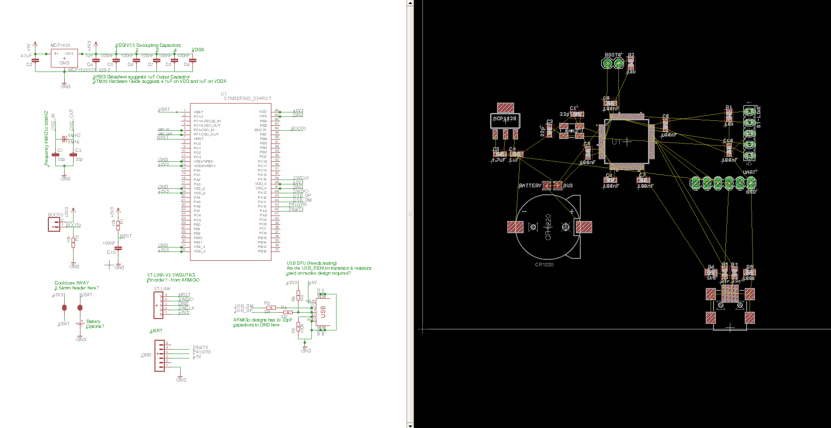
The design so far:
- STM32F303RET 64pin
- 5V to 3V3 Voltage regulator MCP1825 500mA (enough for an ESP8266 I think)
- Decoupling capacitors on supply inputs as in AN4206 best practice guidelines.
- Oscillator
- ST Link Header
- UART Header
- USB DFU (needs testing as above)
- Battery holder footprint for RTC?
- Jumper for BOOT0
Download schematic and board file: stm32hw01.zip (44.8 KB)
I’ve noted a number of ongoing questions I have on the schematic, they are:
- VREG Datasheet suggests minimum 1uF Output Capacitor, STM32 Hardware Guide suggests 4.7uF on VDD and 1uF on VDDA. Should I add all three in locations close to the respective components or is a 4.7uF capacitor near the voltage regulator sufficient.
- Which oscillator frequency do we choose?
- I’ve used a couple of solder jumpers for the RTC Battery / 3V3 supply selector, would a 3pin throughhole header be better (not likely a configuration that will change regularly in a design - solder jumper should be fine and keeps things compact).
- ST-Link connector pin out I copied from Ken’s ARMiGO design, the order is different from the SWD connector on the ST-LINK board, is there a standard to adhere too?
- Should UART reset connect to NRST somehow? BOOT0 needs to be pulled high and board reset for serial upload to work, inserting a jumper and power cycling the board worked fine in testing above, is there value in automating this step?
- USB DFU needs testing, Nucleo reference design has a transistor and 3 resistors connecting the 1k5 pull up to USB_RENUm, The ARMiGO design does not have this, is it needed? Same goes for the 22pF capacitors.
My next steps will be to test the USB DFU again following your suggestions @pb66 and learn more about the onboard op-amps to provide a buffered bias level for the CT and ACAC signals…