The extra resolution would be nice. The downside is that the phase-shift approach shifts an entire ADC (not individual channels), so if you want to use it to avoid interpolation and all that stuff, I think you need an ADC dedicated to Voltage measurements.
Unless here’s no other way, that’s unlikely to be satisfactory to most potential users, in my view. The more flexibility there is, the better. But I can understand permanently committing 1 c.t. to each phase.
But if we have a well thought out modular front end, the choice of physical input to ADC channel might be made there, in which case the software must be capable of mapping to the physical arrangement.
That’s nice to avoid, but it does have one advantage: by organising the maths differently, you can apply it after the event when the rms values, hence the phase errors, are known, which opens the way to real-time correction. But if the timing can be shifted on-the-fly, it will negate that.
Actually, I’m saying assign CTs to phases at runtime, all in software. You can associate a CT with a phase simply by which slot you drop it into in the sequence (apart from a few extreme cases). Or is your concern about those extreme cases?
Nice.. and allows per-channel correction which the ADC triggering solution will never be able to achieve. The other big advantage of going the s/w route to phase correction is it means I don’t have to work out how to write those remaining two empty routines in adc.c to support changing the shift in the other direction ;-).
I think that as long as most are flexible, that should be enough. There will always be that one situation that nobody expected. But to (say) permanently allocate a third of the c.t’s to each phase would be rather restrictive, especially to users who want per-circuit values.
Also remember that not everybody wants 3 voltages, 1 only (UK domestic) and 2 only (US domestic) are also valid, so (again assuming a fully modular front end) one or two “V” channels become free to be used for currents if the hardware allows.
It’s not just the extra resolution either from what I read the sigma adc’s are aimed at removing/reducing noise.
depending on how thw 40 channels are distributed on the f373, it might be possible to get 15 to 18 ct channels on one adc, leaving the other adc to just do Vac, regardless of whether it’s single, split or 3 phase. configuring the pairs will be totally flexible 0-all CT’s per Vac input.
Yes, totally agree. The first example above was to demonstrate how easy that case is, not to mandate that case. A common situation in Aus is to have all your house circuits on one phase, and then later, as you add air-con, bring in a second phase just for that. Later again when you bring in a shed full of power tools, bring in a third phase for that. The above scheme would support that like this:
But I also agree a fully modular front-end makes all these solutions easy, although I suppose it would come down to h/w jumpers Vs s/w config?
STM32CubeMX is excellent for quickly answering questions like that. Just fire it up, select your CPU of interest, and start assigning pins to ADCs over on the left hand panel.
Would I be right in thinking the method of correcting phase errors currently being experimented with, might also accomadate a derived-3phase solution too?
It’d be difficult to support that with the ADC-trigger approach. I’ll let Robert speak to the s/w approach, but assuming he’s hopeful, that’s probably another nail in the coffin for the ADC-trigger approach.
Not sure what you mean by that? Measuring one voltage and phase-shifting to generate a ‘best guess’? I know there are objections and practical difficulties in having 3 a.c. adapters, but there are definite advantages in knowing all 3 voltages.
A big problem with - shall we call it “time displacement” - is the differential phase error between current and voltage depends now on the timing of the voltage in addition to the transformer errors, and that depends on a variable mains frequency. You need to measure it and adjust the delay, or phase lock to it, to remove that variable. So the 3-phase PLL sketch calibrates in much the same way as the single-phase ones, because the timing variable has gone.
(But with a fully modular front end and enough power for some op.amps, it might just be possible to do the “capacitive v.t.” to get the voltages, although that has big uncertainties regarding construction, installation and calibration.)
yes a single ac:ac adapter 3ph solution
indeed, and you will find no one keener than I to use 3 ref voltages, but as you know many users do not go that route, I will never use a single ac:ac adapter 3ph monitor if I can avoid it, and I always do. My interest here is purely to contain the number of FW’s in circulation, I do not recommend using a single ac::ac 3ph solution and I’m well aware of the reasons for that, But still users will want it. To think it is not going to be required would be foolish.
I’ve used “derived-3ph” as a term to replace “single ac:ac adapter 3phase” as it’s a lot of typing, do you have a preferred term? There has to be a simple way of distinguising between “3 ac:ac adapter 3phase” and “single ac:ac adapter 3phase”. “3phase FW” is too vague and will cause confusion
Actually, if you are going the s/w phase correction route, and you don’t mind also correcting for the slight offset introduced by the ADC cycling around from channel to channel, @TrystanLea’s project above might be a better starting place. It has the advantage that it works with a stock shield (no jumper required). You could potentially even productise that and sell more shields. It was only the delayed ADC-trigger stuff that forced me to move the V signal.
Adding the jumper and using a shield are just means to basic tests on it, we would want more than 4 cts and 1ac.
I personally need 3ac’s and 5ct’s per phase minimum. the intension here is hopefully not to be to constrained by anything, start with a clean sheet, decide what we want and use what we’ve learnt to achieve it rather than reuse what we’ve developed already
I actually recommended we order a short batch of a (say) 10 cheap pcb’s with footprints for 18-21 3.5mm sockets and 3 AC’s sockets that we can populate by hand and connect to the nucleo board with jumpers for initial dev testing. That way we can try all the adc routing options.
Yes, fair point. The 1V+4CT shield is just an interim prototype board.
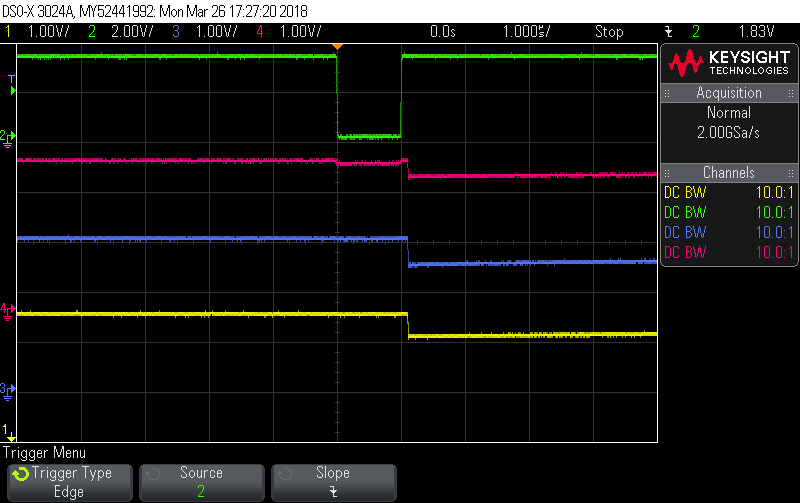
OK, I completed the ADC trigger delay stuff, even if it ends up not being used it might be useful for playing around or calibration. It now supports:
+ve lags (Current ADCs are launched early, Voltage ADC is launched late)
-ve lags (Voltage ADC is launched early, Current ADCs are launched late)
0 lag (all four are launched at the same time).
In these traces Red is the Voltage ADC input, Blue and Yellow are two of the three Current ADC inputs. Green is the ADC trigger signal:

start_ADCs(10);

start_ADCs(-10);
start_ADCs(0);
I’ve also added access routines to the CPU temperature and the Vdda reference voltage (since we were sampling them anyway), and a dump facility in power.c in case you want to look at the signals instead of doing power maths on them.
I think that’s about it, and I’ve tar’d it all from one level higher, so hopefully no build dramas this time.
txshield_demo_5.tar.gz (883.2 KB)
Paul in this thread you pointed out that STMDuino now gives support for the STM32 chips in the Arduino environment → Best hardware option for multiple CTs & WiFi - #24 by fahrvergnuugen
It would be great if the code you guys are working on could be made into an Arduino library - say, CT-STM32 or STM32MainsPower or some such name which can be used like say OneWire, i.e. by creating an object with parameters that would specify the inputs etc. or at least have the most common configurations pre setup so to speak?
Also just want to say this has been one of the most interesting, informative threads for a long time. Please keep documenting things as you go along. Just wish I had more time to be able to experiment along with you guys. Can we have star ratings for threads? 
Simon
PS If there’s so much spare capacity in the system and if this becomes the new standard for emon processor then maybe we could get them mining bitcoins in the background to pay for our emoncms.org accounts. 
I’ll drink to that. It’s the first thing I read after logging on! ![]()
For info, this is the latest version (v5) of dBC’s txsheild_demo_5.tar.gz, which as can be seen, now captures & prints CPU temperature and Vdda (the analogue reference voltage).
The readings are obviously wrong as I’ve just hooked it up with no CT’s or AC input into the shield at the moment, just for a quick screenshot.
Moving forward nicely!
Paul
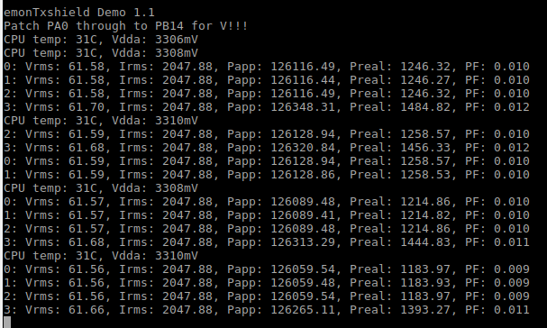
Those Irms values look very good… almost too good to be true. Do they ever change at all? I’m assuming that’s the mid-rail? I’m not quite sure what to make of Vrms but it looks pretty solid too.
I struggle with headphone jack schematics. Can someone advise what the expected behaviour is when nothing is plugged in please?