In case anyone or any future readers was wondering why I was emphasising disproving, it’s a better way of gaining an understanding of something. And it’s more fun I think.
I found it funny, and it was intended as a joke. Maybe… The older the established theorem the more ridiculous it is to try disprove it. If that becomes a Razor I’d like to be named after it when I’m dead, thanks.
I think related to your suggestion @dBC… why the parallel resistor treatment was surprising to me. Effectively they end up looking like this, with a variable voltage source, is this right?:

It’s not how they’re really arranged. However, it is useful to think of it this way though, remembering the variable voltage source thing.
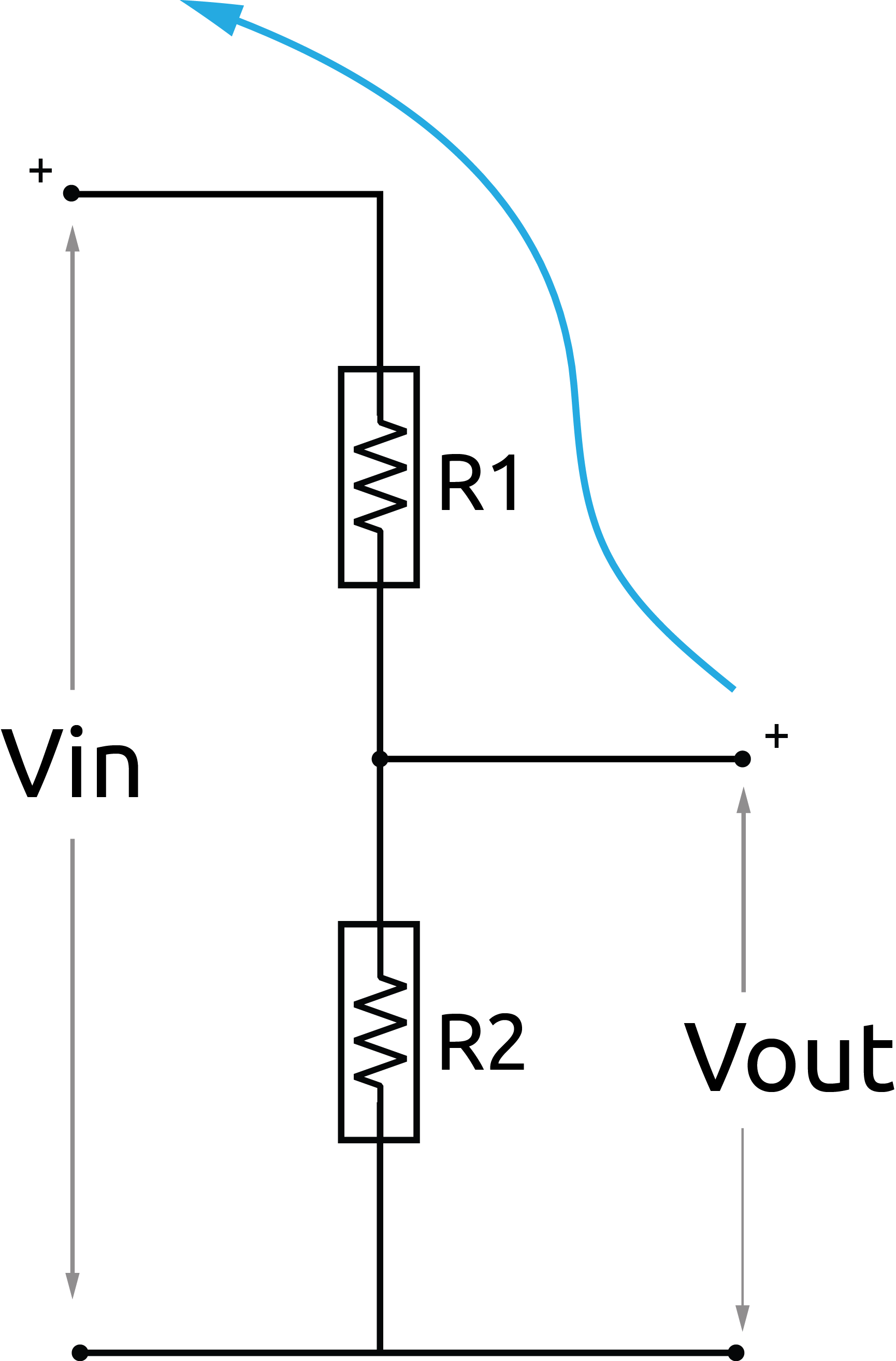
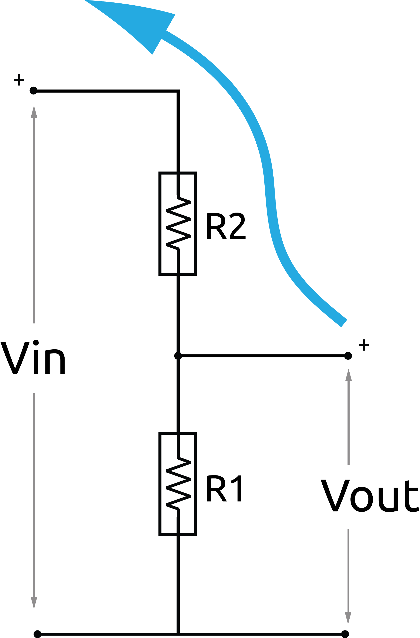
When R1 and R2 are swapped no difference is made to the overall impedance of the parallel resistors. But the voltage across R3 is varying because of the potential divider arrangement, say if R1 is 1MOhm and R2 is 10k, for example.
What threw me was an expectation that if the source impedance was the same, that for some reason the current path would change when the resistors were swapped, which is not true. The path is the same (the same direction of electrons flowing from negative to positive), but the swapped resistors changes the amount of the energy available between R1 and R2, the energy as e.m.f. .
This is all really obvious, but I had to detach the current and voltage to a greater degree in my head to understand why I saw what I saw. I think the confusion only arose because V, I and R are so closely related.
These illustrations have helped me understand swapping R1(1M) and R2(10k) and the change in flow, which is proportional to the change in e.m.f. .