Hello, I’m looking for help in understanding a physics problem.
From classes and from reading again this evening I understand the source impedance relating to R1 in a voltage divider.
If electrons in a circuit flow from negative to positive, why isn’t the source impedance defined as R2?
Perhaps a related question, does R2 define the source impedance in certain circumstances?
I’m correlating to Thevenin’s Theorem like this:
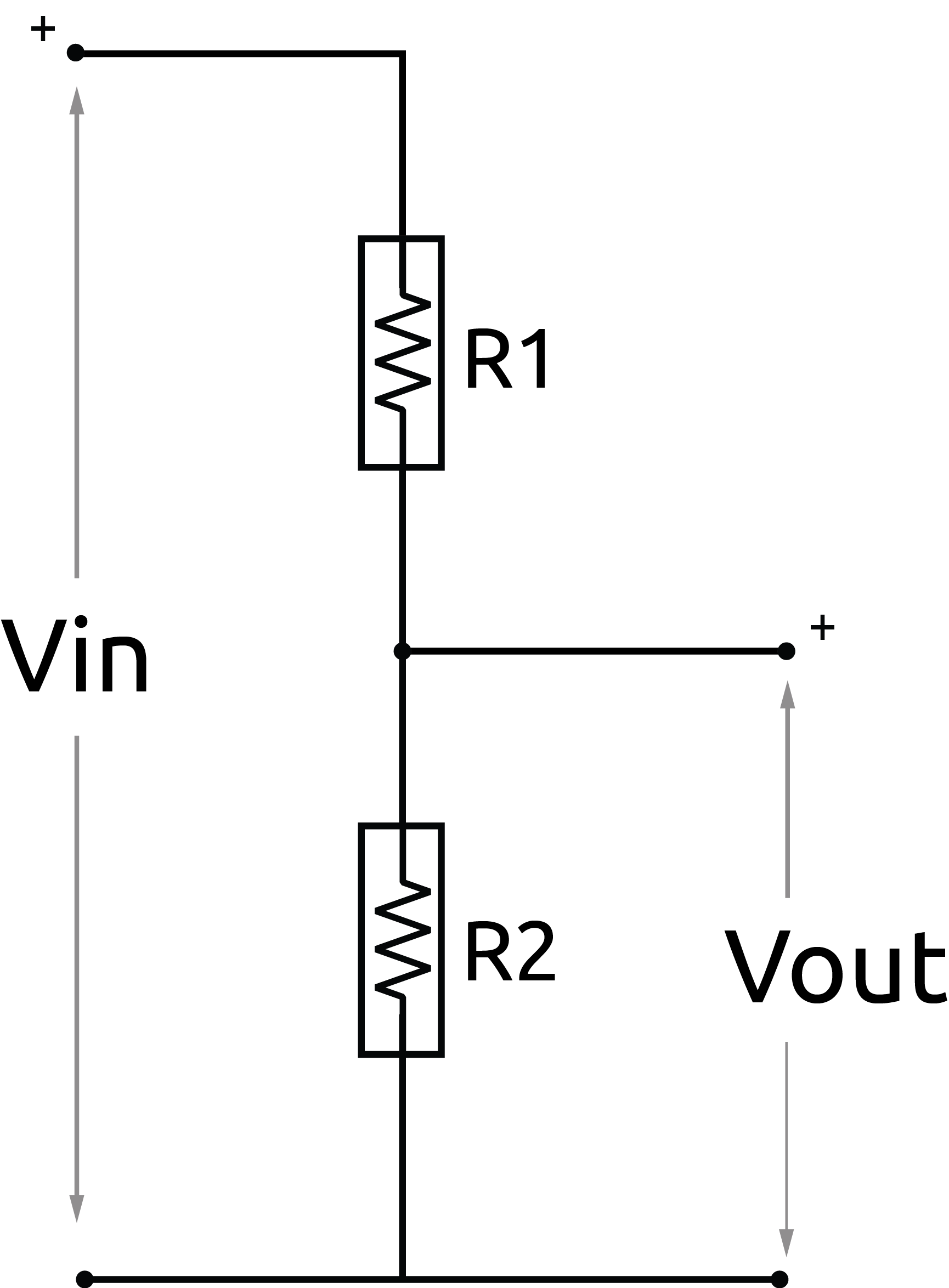
Vin in my diagram is Vs, R1 is RS, and R2 is RL. I’ll attach an image depicting the theorem we can refer to:
Yes, exactly. The impedance seen by any load connected across Vout.
In that case, no. Your Vs, R1 & R2 are the “Linear Network” inside the green box whose equivalent is VS & RS. (And that VS is not the same as your Vs.) RL is:
Yes I see that now.
I realised another way of seeing the problem, where anything connected to Vout changes the current path in relation to R2, in which case R2 must be included in the green box, as part of the source impedance. That’s a tricky one.
Not tricky at all, those are two completely different situations.
With no other connection in parallel with your R2, R2 is the load. You have Vs, R1 & R2 all connected in series.
When you connect a new load in parallel with R2, then your circuit can transform into its Thevenin equivalent circuit, and you’re back to square one with a voltage source (your Vs but with a different value) and its “internal” resistance (your R1 also with a different value), and a new load (equivalent to your R2) all connected in series.
I agree it’s not tricky once realised. My understanding of electron flow and the habits of placing large impedances at R1 have confused me.
The question which follows is, when transformed into the Thevenin equivalent, what is the new source impedance? What’s the maths necessary to turn R1 and R2 into a new impedance value? Are the resistors simply added together as a series resistance for a total impedance value? (this doesn’t make sense intuitively) Or is it calculated from looking at the resistors in parallel? (again, this doesn’t make intuitive sense).
There’s the next step of understanding I’m missing to work out the new source impedance…
(Only go as far as, but not including, “Conversion to a Norton equivalent”. A c.t. is a current source, so Norton’s Theorem, which is the dual of Thevenin’s, is extremely important when dealing with current sources.)
To “intuit” that, you just need to consider that the source impedance of the voltage source is 0. So the two resistors in the divider are actually connected together at both ends… on the left at the battery and on the right at the load.
Well, I tried undoing the 150 years or so of T’sT. I did not get far with that, however, I did enjoy the process, and am now a keen advocate (I’m laughing hard right now).
I started off with experimental observations, and worked my way towards calculating results in advance.
Sometimes satisfying to revisit the fundamentals
So, my interpretation of electron flows, and fully understanding why the theorem works hasn’t all clicked together. But I’m happy to accept that it works.
Looking at it in terms of voltage source is the way.
That location in between R1 and R2 is simply an area of e.m.f. . Driving current through any subsequent load, preceded by its own resistance.
I haven’t reconciled this with the concept of electrons flowing from negative to positive, got some thinking to do.
In case anyone or any future readers was wondering why I was emphasising disproving, it’s a better way of gaining an understanding of something. And it’s more fun I think.
I found it funny, and it was intended as a joke. Maybe… The older the established theorem the more ridiculous it is to try disprove it. If that becomes a Razor I’d like to be named after it when I’m dead, thanks.
I think related to your suggestion @dBC… why the parallel resistor treatment was surprising to me. Effectively they end up looking like this, with a variable voltage source, is this right?:
It’s not how they’re really arranged. However, it is useful to think of it this way though, remembering the variable voltage source thing.
When R1 and R2 are swapped no difference is made to the overall impedance of the parallel resistors. But the voltage across R3 is varying because of the potential divider arrangement, say if R1 is 1MOhm and R2 is 10k, for example.
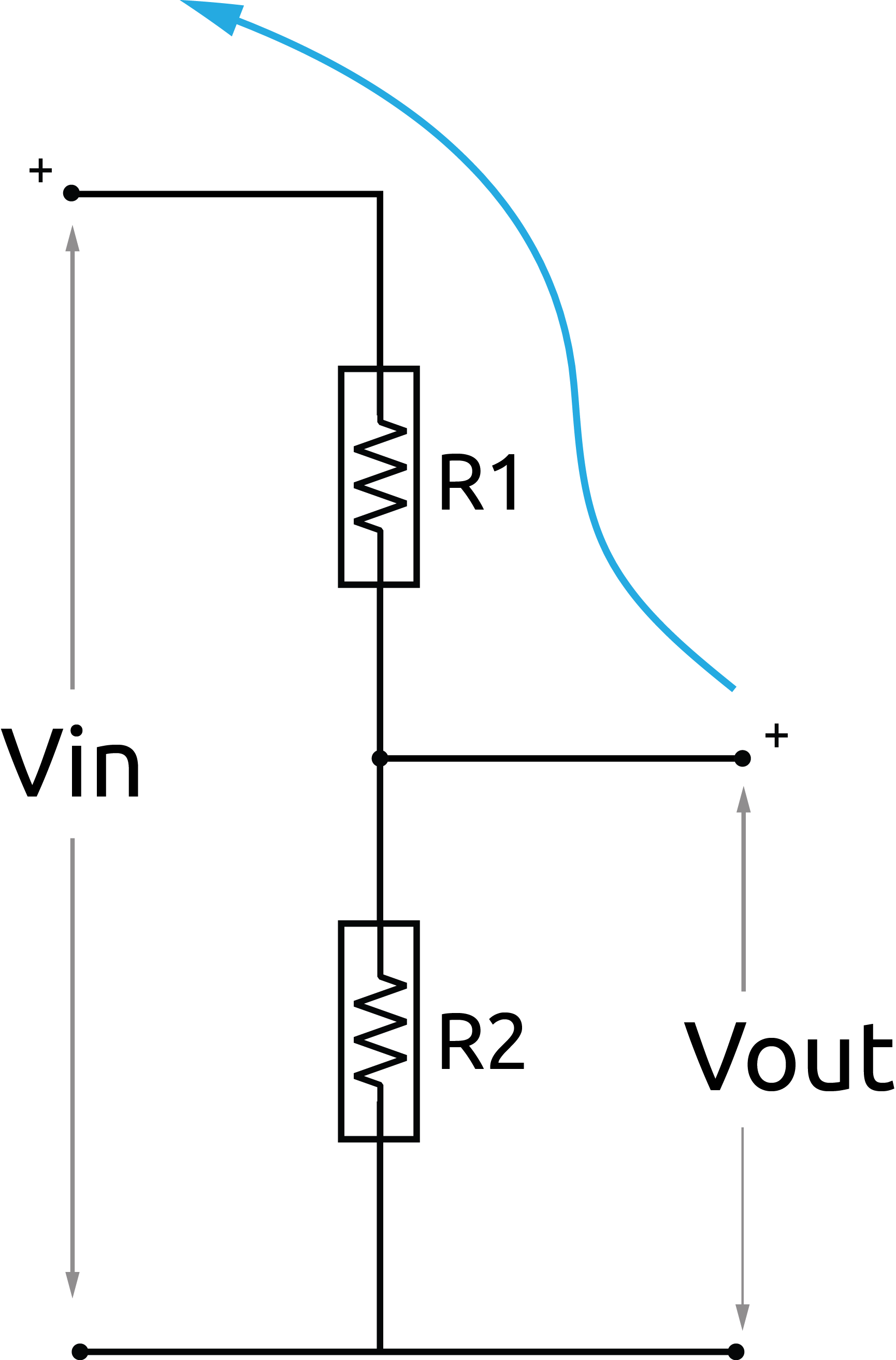
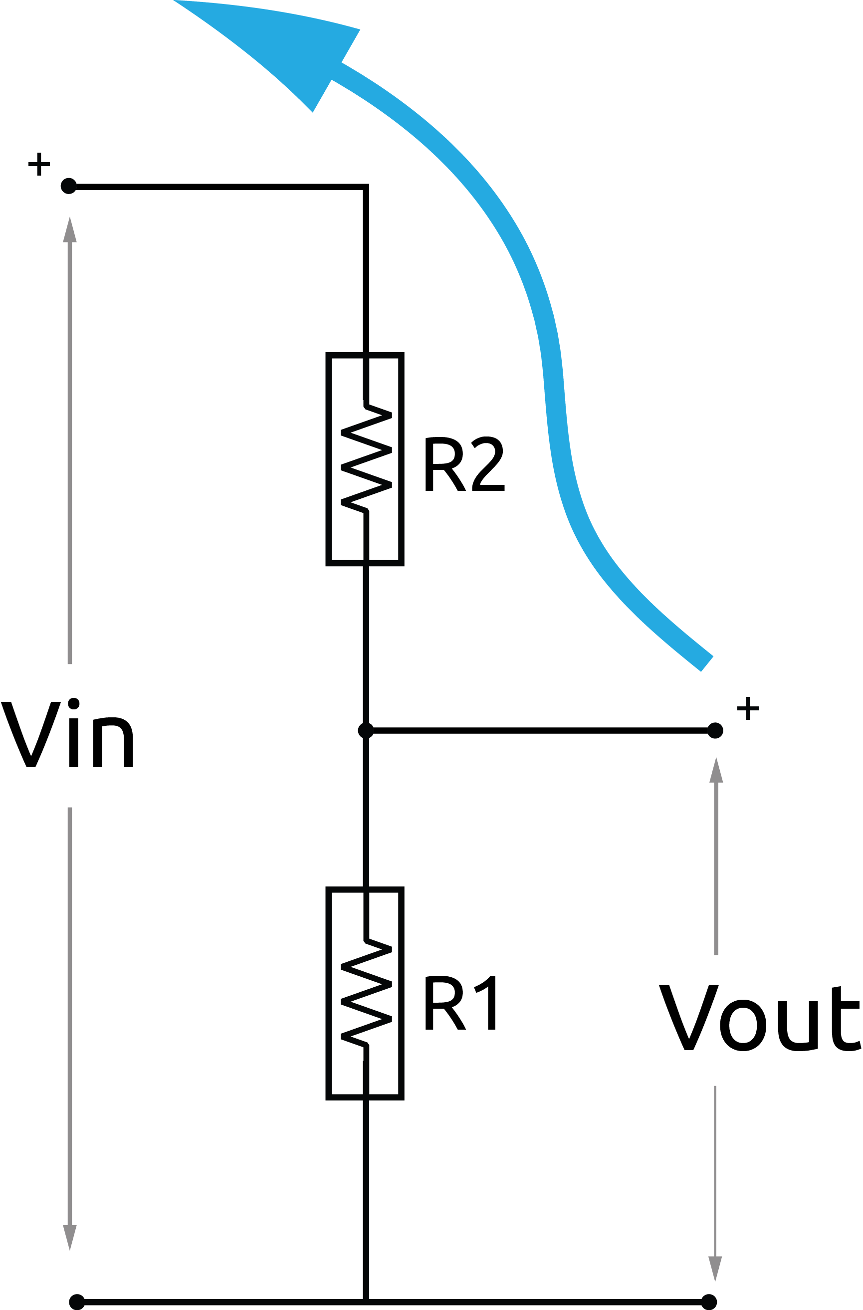
What threw me was an expectation that if the source impedance was the same, that for some reason the current path would change when the resistors were swapped, which is not true. The path is the same (the same direction of electrons flowing from negative to positive), but the swapped resistors changes the amount of the energy available between R1 and R2, the energy as e.m.f. .
This is all really obvious, but I had to detach the current and voltage to a greater degree in my head to understand why I saw what I saw. I think the confusion only arose because V, I and R are so closely related.
These illustrations have helped me understand swapping R1(1M) and R2(10k) and the change in flow, which is proportional to the change in e.m.f. .
No, but if you re-read the theorem, it says that you remove the voltage source and replace it by a short-circuit, and you can do that because the ideal voltage source can supply infinite current, which implies zero internal resistance/impedance (as dBC wrote). And when you do that, the resistors are clearly in parallel.
Whatever you do, don’t confuse energy and e.m.f. Those are entirely different quantities.
Returning to
I only worry about electrons flowing when I’m thinking of vacuum tubes (either thermionic valves, cathode ray tubes or travelling wave tubes), and sometimes semiconductor junctions. The rest of the time, I think in terms of conventional current. I recommend you do the same. Most of the time, it’s just a sign reversal and it’s a lot simpler.
Understood! e.m.f. is of course potential energy. Joules per Coulomb I remember… Thus, the Coulombs must be delivered somewhere to get the Joules.
I can really see where that recommendation comes from now. Flowing electrons are all well and good but they did trip me up, and I guess don’t really add anything to the modelling of electric forces. Of the three you mention I only know about cathode ray tubes, the other two sound proper awesome though.