I had my ASHP heat pump installed in May, and naively thought that having a heat meter would be enough to be able to calculate the CoP and measure performance, which is possible but taking daily readings is a pain and doesn’t provide enough resolution to monitor anything meaningful.
What I’d like to do is buy the Level 3 heat pump bundle to be able to monitor performance. But I don’t want to do this if I can’t get my existing heat meter to talk to the emonHP. The Superstatic 749 that I have has 2 pulsed outputs. How do I hook this up to the emonHP?
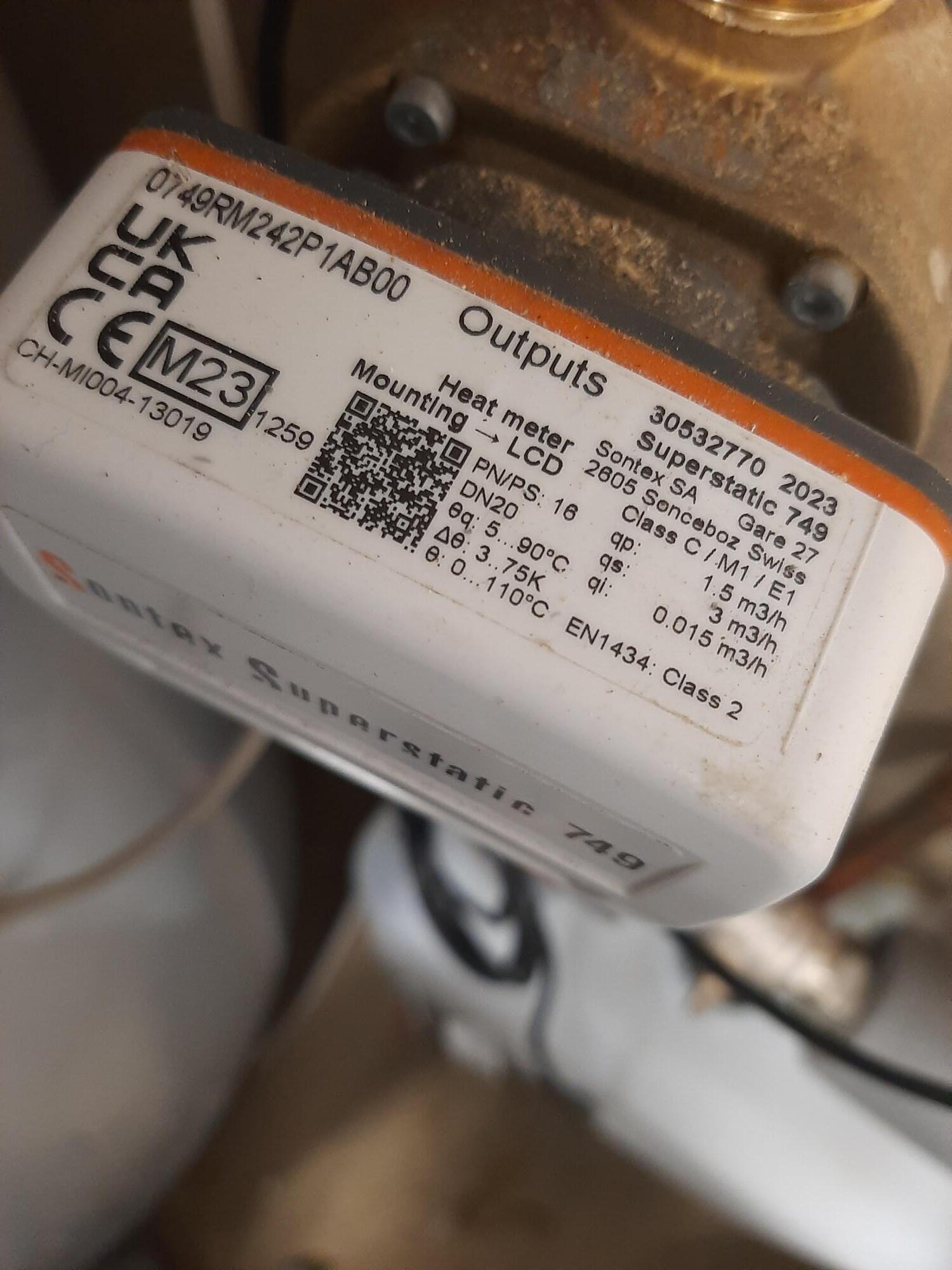
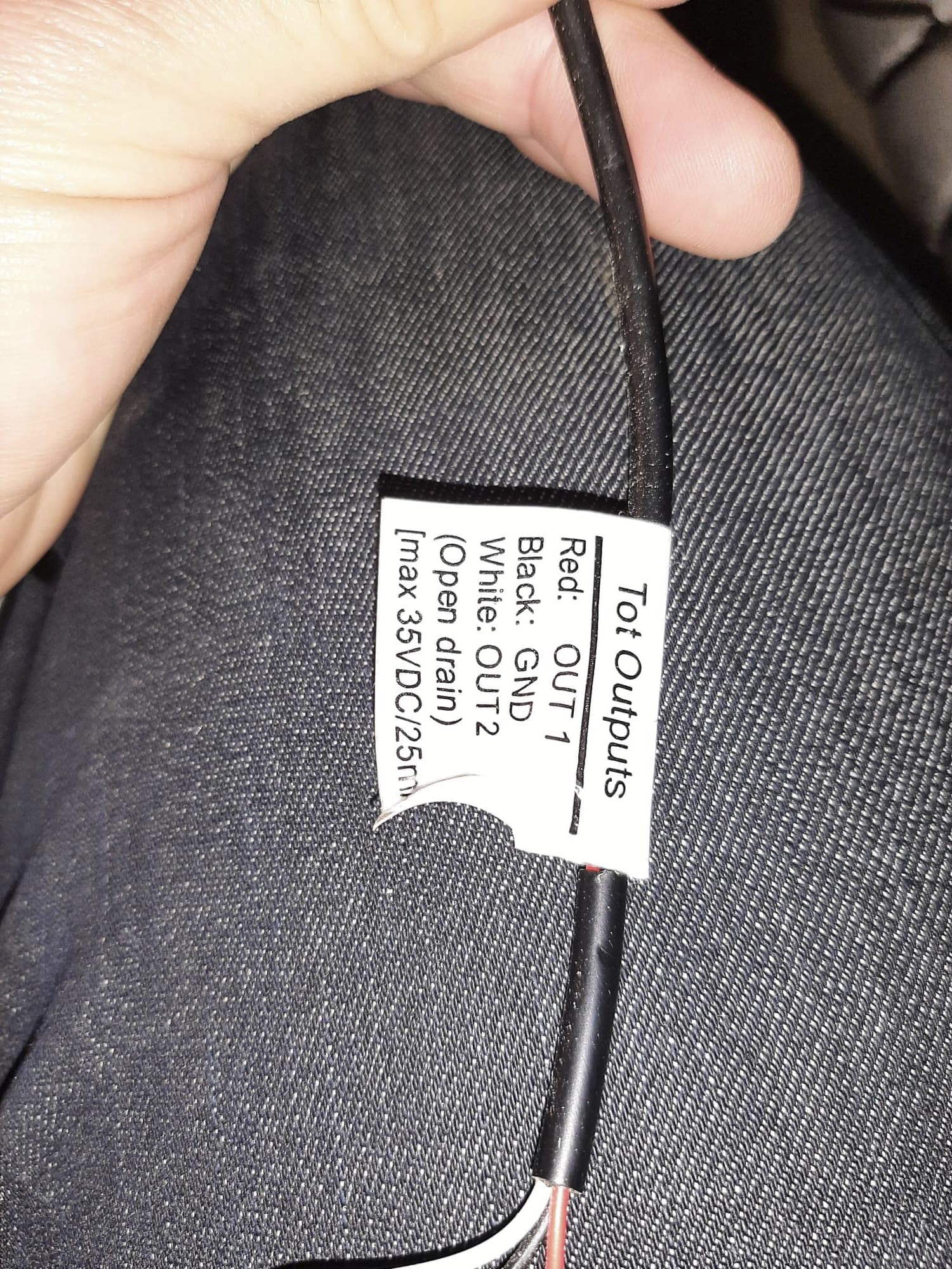
Attached are pictures of the meter name plate, the output cable and the extract from the manual.
Another request for help from anyone with a Sontex meter.
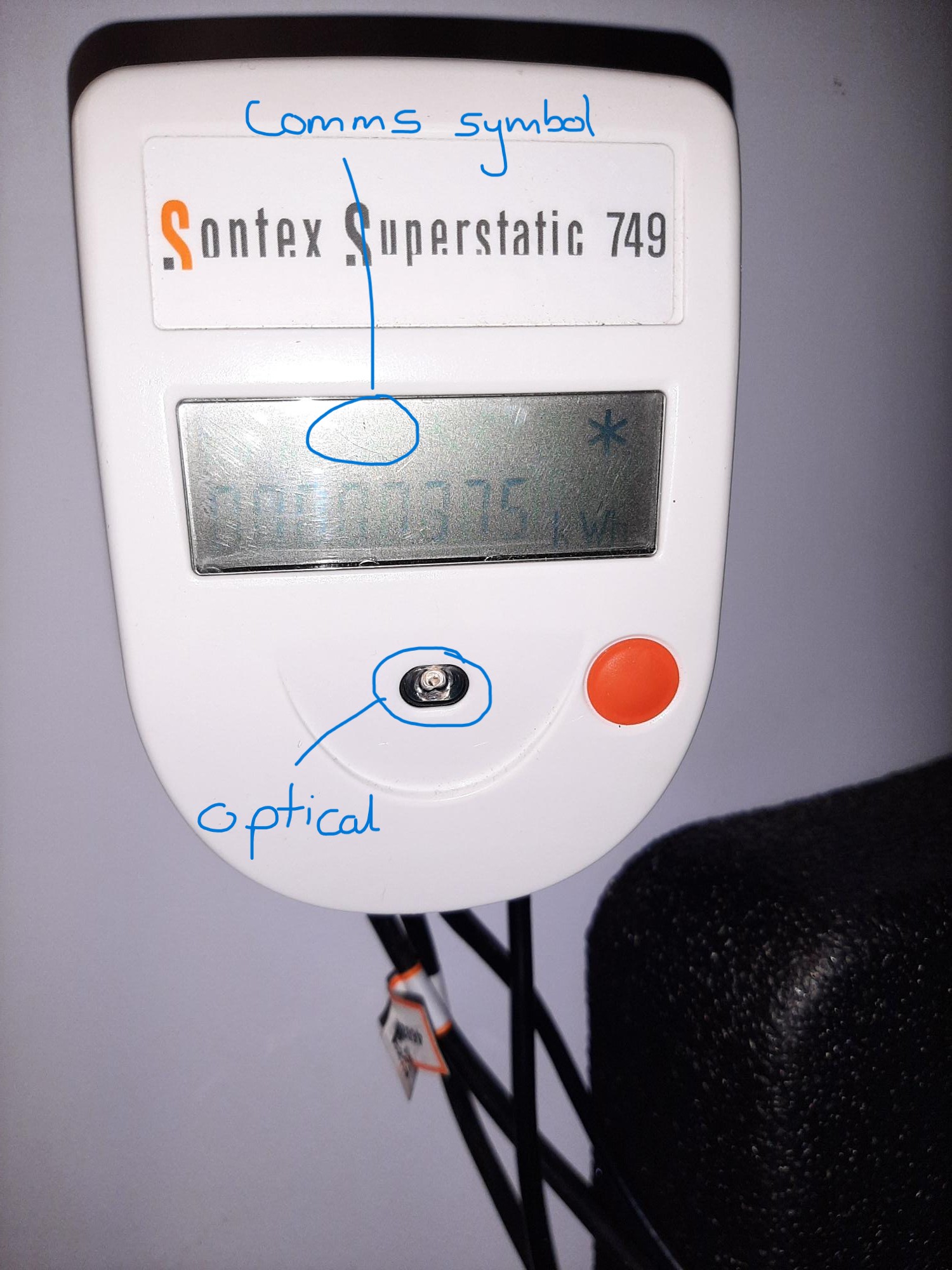
I have an EmonPi2 installed now and mostly set up, but I still can’t get an output from the sontex 749. It doesn’t have an m-bus so that is not an option, leaving me with a pulse output and an optical output. I brought an optical sensor as part of the EmonPi2 package. I have tested it with a torch and it’s counting correctly, but it will not pick up any signal from what I think it the optical output on the front (the little LED in the centre). I don’t think the Sontex 749 is flashing. . I spent a good deal of last night in the dark watching the meter reading change as it counts up the cumulative kWh, but could see no flash. I’m thinking it’s either not activated, not functioning or infrared. I have been through all the menus to see if there is an on/off activation but can see nothing.
I thne attempted to repalce the optical pulse counter with a hard wired output from the meter. There is a ‘communication’ symbol that appears to flash on the main LCD screen every 0.1kWh, so it looks like there is a pulse output. But I simply couldn’t get any count on the EmonPi2. I tried various wiring combinations of output 1, ground and output 2, but I’m not sure what I’m doing and really don’t want to damage the EmonPi2 either.
Has anyone managed to get an output from a non m-bus sontex meter? I’m almost at the point where I give up and replace it.
Hello @PJMOODY the optical output on the front of the meter is for configuration as far as I understand. We use it to configure the meters (e.g setting glycol calibration) using a sontex software tool.
The pulse output on the sontex is an open drain pulse output, you could connect this to the emonPi2.
I think reading the datasheet you may only need to use OUT 1 (heating energy).
The easiest configuration would be to connect this pulse output to what is labelled as the analog ADC input on the emonPi2, see the example given here for the optical pulse sensor: Other sensors — OpenEnergyMonitor 0.0.1 documentation.
The open drain pulse output will need a pull up resistor between the pulse pin and 5V I believe.
I wonder if there’s any way to convert or upgrade the meter to an MBUS output version it gives a lot more information… I will ask @glyn.hudson
The optical port of the sontex is an infrared port for configuration not an led that flashes with each output pulse. That won’t be useful to you I’m afraid.
Just looking at energy won’t tell you much that’s useful. You really need temperatures and flow rates from the mbus to know what to do with the system once you have the cop.
Replacing the meter for a unit with built in wired mbus may cost less than you expect. You’ve already got the hard parts done (unions and probe pockets in place).
Also you have a 12 kW heat pump with a 1.5m3/hr heat meter? That’s probably on the small side with regards pressure drop. Or if the property maintains temperature ok the heat pump is probably on the large side.
Many thanks for getting back to me. The operating manual has finally become clear. The optical interface is not what I thought it was.
I’ve set the EmonPi2 up so that I can get all the temperature readings and I appreciate the flow rate would be useful, but the total heat output calculated by the heatmeter will be the best I can get at the moment for calculating the CoP. Had I known about the m-Bus option I would have specified it before the install. I don’t think changing the meter is an option unless I get the installer to change it as I don’t want to void the warranty from Vaillant. I have also spoken to a Sontex sales rep to see if I could just change the head and leave the flow meter in place, but this isn’t an option.
The installer insisted on using glycol in the heat pump, so the heat pump circuit only heats the hot water cylinder and a heat exchanger (which transfers heat to the house heating circuit). I agree that the flow meter is on the small side and will have an excessive pressure drop. I wish I had known these details last year.
We do have a 12kW heat pump, and it’s running pretty hard in this weather (we live in an 1890 granite solid wall house, with very little insulation until last year, on the east coast of Scotland) . Yesterday the Vaillant app claims we used 100 kWh and generated 225kWh giving a CoP of 2.25, although it was -2°C for most the day. The system was running at about 48-50°C. This highlights that I don’t have enough surface area in the house for it to run at 35-40°C when it’s below 0°C outside, and I need to improve the insulation. I’ll work on both these this year.
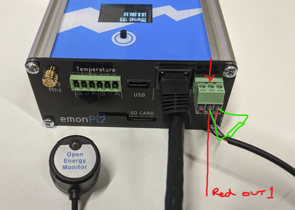
Just so I understand. I should try and connect the Red Out1 to the ADC input and then a pull up (or down?) resistor between the 3.3V and the ADC as I have drawn? What resistor, 10K?
Apart from this last hurdle, I have all the CT monitors and temperature probes installed, and I’m just building the charts and displays to show the heat pump, solar and battery performance. The EmonPi2 and Emoncms, etc, is very good.
I have spoken to DMS https://www.dmsltd.com/ and they have advised that I can’t just change the head. I think that is because the head is calibrated to the flow meter, but not sure (I’m still not convinced it’s set up for the glycol mix we have. The installer hasn’t been very helpful since I started asking detailed questions. So the output might be junk anyway). If there is a way to change it then I’d be up for it, although it’s a sealed unit, it’s only for my information (i.e. not RHI).
Hello @PJMOODY yes your last diagram is what I had in mind, a 10k pull up resistor in that position should be correct. Red out 1 and then ground to the left of it.
You will need to upload the emonPi2 DB single phase, 6 channel firmware, pulse on analog input, lowpowerlabs firmware via the Admin > Update > Firmware tool as well to enable this.
If the OP doesn’t want the hassle of draining down and physically changing the flow meter, they could just buy a MBUS Sontex 789 and swap the PCB. All the sensors and the flow meter are pluggable. sontex doesnt sell PCB separately though.
It’s taken me a few days to get the resistors. I’ve tried a 10k and 100k pull down resistor and the EmonPi2 is not registering any counts. I did update the firmware too, but unsure if there are any other settings that are required.
Would updating the firmware disable the EmonTH I have? I’ve tried removing and replacing the batteries. I’ll have a look through the forum to see if there is a fix.
Great idea. I’ve had a think about this I can only source a new meter that I’d have to butcher. I’m reluctant to do that as knowing my luck I’d end up with 2 non functioning meters. If I’m going to buy a new meter, I’d bite the bullet and replace the one I have, probably in May once we are less reliant on the HP for heating. There is also the warranty question I’d need to clarify too. In the mean time I’ll keep my eye out for a second hand 789 or 749.
Pulse output function
If ordered the Superstatic 749 offers the possibility of integrating two open collectors pulse outputs which can represent hot energy, cold energy or volume.
Elsewhere, it refers to
Open drain (MOS Transistor)
but that’s still the same configuration.
This means you wire the common (Sontex) to GND (emonPi), the collector/drain to the input, and the pull-up resistor between the input and the 3.3.V.
Unfortunately, I can’t see a diagram indicating which wire/terminal on the Sontex is common/gnd and which is the pulse - and this matters, you must get it right.
It looks like the Law of Natural Perversity strikes again. The only slight clue is “volume” is mentioned second here - assuming you have it all along, as the pulse outputs appear to be optional:
• Two pulse outputs either heating or cooling energy consumption and
volume, or heating and cooling energy consumption.
I have tried the output2 and that doesn’t work either. I think at this point I give up as I have no idea what else to try. I’ll get and install a new, larger capacity, heat meter over the summer
That picture of the lead end with the label - did the lead come with the meter, or did you get it separately?
Does your emonPi count pulses if you create them manually, i.e. with your pull-up resistor connected to the input (middle) pin and the right-hand (3.3 V) pin on the Pi’s connector, use a short length of wire to connect the input to GND (middle to left).
If no, is the sketch in your emonPi2 front end set up to look for pulses on the analogue input?
If the Pi does see pulses, connect the meter Common – GND (left), Output to Middle, keeping the pull-up resistor in place, and measure the voltage GND - input. I’d expect to see about 3.3 V, except when there’s a pulse – and unless your meter responds quickly, you probably won’t see a pulse with it anyway.
The last thing I can suggest - do you have a LED to hand - any colour, preferably red? If you have, and a 9 or 12 V battery, connect the led and resistor in series and connect them across the battery, the flat on the LED/the short lead towards the battery negative - the LED should light. Put the Sontex in series as well, common to battery negative again, and watch for a pulse. It won’t be very bright even with the 10 kΩ resistor (it’ll need to be dark, and you won’t see anything with the 100 kΩ) but any resistor down to 330 Ω will be OK and the LED will be brighter the lower the resistor value (no emonPi required!).
The picture with the lead end came with the meter. I have checked the part numbers and am 99% sure that it’s a pulse output only. On the screen there is a communications icon that does flash once every few minutes.
I’ll test the EmonPi2 counts pulses tonight if I get a chance. With the optical pulse counter, I was able to use a light to test. SInce then I have updated the firmware as instructed by Trystan in the post above. How do I check the sketch (I’m guessing this is the same as firmware)? I’ll have a look through the admin to see if I can find it. As a note, since I completed the update the EmonTH is not longer visible to the EmonPi2.