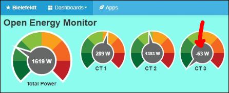
Our emonPi has so far only shown positive power, except for a less negative display when there is almost no load on the phase (3) where it shows -50 W (oven and stove). If I completely turn off the group, it goes to 0.
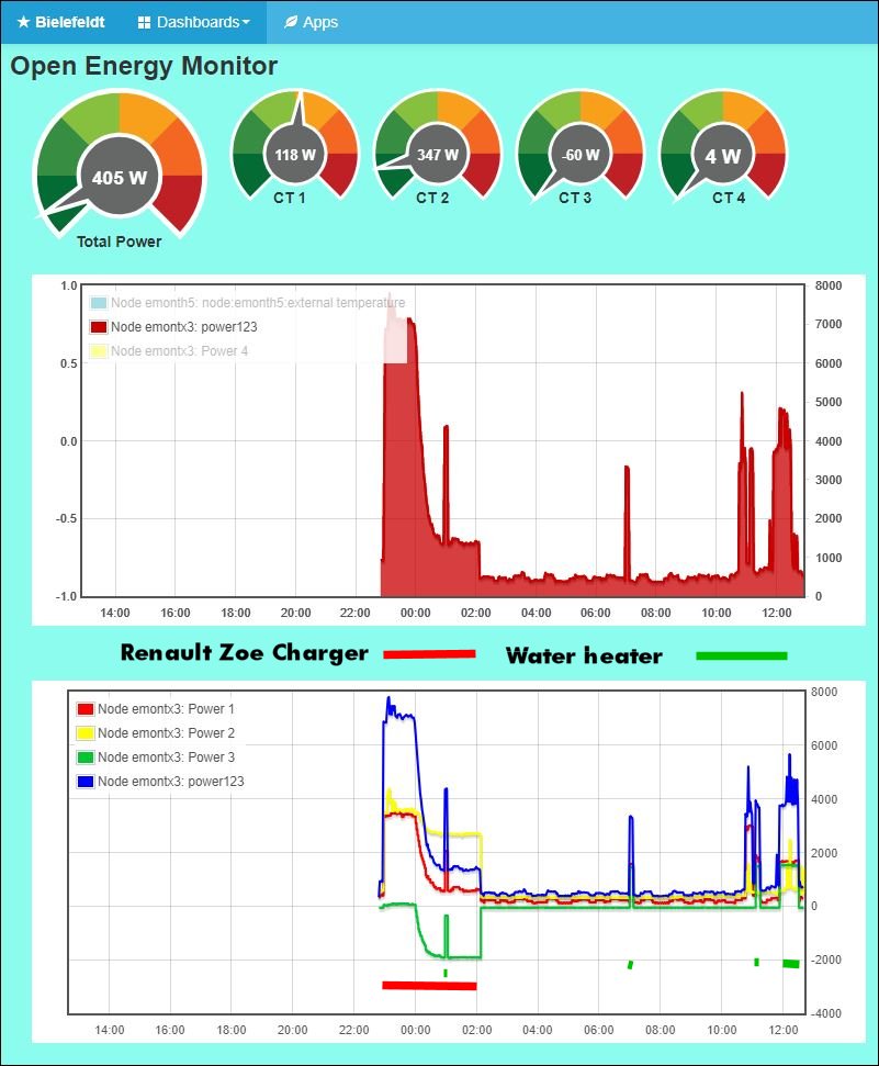
With the connection of the Renault Zoe charger, we find that Phase 3 goes negative, while it is positive when our water heater is active. The Water Heater run at two phase (3 KW)
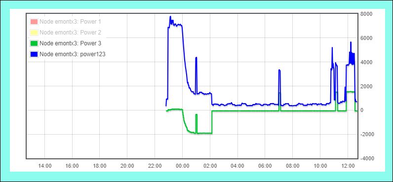
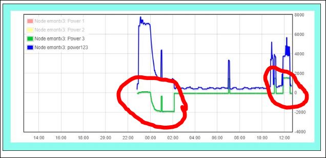
Below we see that when Renault Zoe charge, goes Power 3 negative.
When the water heaters run, the same Power 3 goes positive.
As a first guess, I’d say that the third phase is not calibrated properly and a low power factor on that phase is making it appear as a negative power.
There might be a problem with how emoncms processed the numbers, or there might be a problem with the numbers before they reach emoncms. Without knowing how those numbers get into emoncms, and being able to demonstrate that they are either correct or they are not, there’s little anyone can do to help you.
So, which sketch are you using in your emonTx3? Have you demonstrated that the current, power and power factor are correct for each phase at the emonTx?
So you are using the “standard” sketch, but you refer to “each phase”. Do you have a three-phase supply to your house? See Learn→ A.C. Power Theory → 3-Phase Power for pictures of single-phase and 3-phase meters if you do not know which you have.
If indeed you do have a 3-phase supply, then the “standard” sketch should always give incorrect readings on phases 2 & 3 (Phase 1 is defined as the phase that the a.c. adapter is on.) You need the 3-phase PLL sketch to get correct values on a 3-phase supply.
Dear Robert
I had the view that it only had significance in relation to the Power factor. I learn something every day
Tomorrow I will update the sketch of my emonTX3 to the latest 3-phase PPL sketch and see how it will behave.
No, if you are reading Phase 1 correctly, Phase 2 and Phase 3 will both read -0.5 × the value they ought to read, even with a pure resistance as the load. Look at the rotating phasors on the ‘Learn’ page, the length of the yellow and blue arrows projected onto the red arrow is half, and in the opposite (negative) direction.
As previously suggested, I think it is worth going back to basics and checking the overall system. I would turn off all load then run a ‘known’ resistive load like a jug on each phase in turn. Repeat with everything turned on and look for the step change when the jug is on. To check CT clamp accuracy you can put all three CTs on one phase – for a purely resistive load two will read half the watts of the other – roll the CTs to different inputs (eg CT 2 to input 1) and you should get very similar results. When I tried this all CTs were within 0.5% of each other, and within 0.5% of an EgoPlus (quoted as 5% accuracy).
If you’re looking for something more obscure there can be measurement issues whenever a load is connected phase to phase on a 4 wire system:
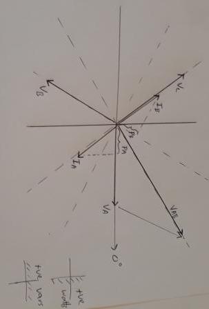
Consider a two phase purely inductive load connected between A and B phases. The voltage that drives a current through this load is VA – VB, shown as VAB. This causes a current 90 degrees lagging VAB, IA, and its return current IB 180 degrees opposite to IA.
The emonTx doesn’t know how the load is connected, all it can see is a current IA that that lags its measured voltage VA by 60 degrees. Similarly, IB lags its corresponding voltage VB by 120 degrees. Say the current is 10A, then A phase records 230 volts x 10 amps x Cos 60 = 1150 watts and B phase records –ve 1150 watts. C has no current so records zero watts. The sum of all three phases is zero watts – exactly what you would expect for a purely inductive load. This is what is seen with old disc meters and a transformer type arc welder connected between two phases drawing energizing current only – one meter spins forwards and one backwards and the sum is the correct energy usage (not cool if the meters have reverse running stops!). Anything worse than 60 degrees lagging will cause one phase to read negative power.
I would be curious to see a schematic of the charger – is it star or delta connected or is there active voltage control or power factor control that is causing a strange power factor on one phase. The hot water system is unlikely the issue, but you mentioned it is connected phase to phase so that does raise a question mark (a long bow – but could CT3 be reversed so it’s actually the hot water giving negative power due to the issue described above, but it would have to a fairly dodgy heat pump type to give that sort of phase shift).
My apologies for the hand drawn diagram – hope it gives an idea of what I was getting at.