This is my first post and i am trying to find the solution for almost 3 days. I have sct-013-000 100A:50mA current sensor and i successfully connected with Arduino and measure the current of 40W bulb. It is showing around 20mV in serial port. Now my question is how do i cross check the value using multimeter?
When i connect the DMM probe to tip and sleeve(without connecting to arduino and burden resistor), 40W bulb is on and put DMM on AC current mode nothing showing up in display. But when i change the mode to AC Voltage i am getting around 176mV.
If i connect the arduino circuit and burden resistor then the AC voltage (either between tip and sleeve or one end of burden resistor and arduino ground) is showing up 0V. if i change DMM to DC Voltage and measure it from one end of burden resistor and arduino ground i am getting around 2.5 voltage which i guess coming from Arduino power.
Now my Question is
How do i measure Current sensor Current Amps using DMM when light is on?
What is that 176mv? did i use that to find current?
I want to cross check everything using DMM and how do i do that?
Please explain in detail. I am little new to electronics. Sorry if my question is absurd.
No, it’s not absurd. What you have probably not realised, is the c.t. is a current source.
So it behaves quite differently to something like a battery, or the mains electricity supply, or a 5 V USB power pack. Instead of providing a constant voltage (1.5 V d.c. 230 V a.c, 5 V d.c. etc), it provides a current that is proportional to the (in your case) the lamp current. If it can’t provide that current (when your DMM is on the voltage range - you DMM takes almost zero current from whatever you are measuring) then the c.t. tries to generate whatever voltage it can to make that current flow. In the case of the YHDC SCT-013-000 (and many other small c.t’s), there’s internal protection to make sure you come to no harm. But with a large industrial c.t., you could have a dangerous voltage if you don’t have a “burden” for the current to flow in. As an aside, a c.t. is always safe when you short-circuit it. It might not be safe if you open-circuit it. This is exactly opposite to a voltage transformer - the sort most people know about.
Unfortunately, that voltage does not mean very much. The c.t. is trying to generate the highest voltage it can to force the current it is trying to generate through a nearly infinite burden (your DMM), so it’s under great stress as there’s nowhere for the current to flow.
Now what current do you expect to measure? Your lamp is 40 W, that’s about 170 mA. You are using a 100 A : 50 mA c.t, so you’ll get what current in the secondary winding? 170 mA ÷ 100 A × 50 mA. Can your DMM measure that? That is probably why you measure zero on the current range.
That current you’ve just calculated, but could not measure, is flowing in the burden resistor. What voltage do you expect across it? It’s the current × 33 Ω. Can you measure that voltage with your DMM?
Correct. Read about that here. It is the “mid-point voltage” that you measure on the d.c. range of your DMM.
Finally…
You’ve probably guessed what your problem is now. Almost everything you are doing is right, but for one thing - you don’t have enough current flowing in your lamp to measure it!
Your c.t. is designed to work up to 100 A. We know it works reasonably well at 1 A, but below that, it gets inaccurate. So if you use something like a 2.5 kW heater (10 A or so), you’ll see something with your DMM. And another trick: If you wind the mains wire through the c.t. several times, you multiply the lamp or heater current by that number. So if the wire to the heater goes through 4 times, you’ll read about 40 A on your Arduino.
There’s a lot of useful information for you in the “Learn” section.
Or, if he doesn’t have a 2.5kW heater to hand, he could do as I did.
Since a 40W lamp doesn’t draw much current, I used 60 turns of AWG 20 wire (0.5176 mm2)
on a split-core CT connected inline with the lamp, to get an effective load of 2.4kW.
Thanks Robert for your detailed explanation. Now i can understand more about my problem. I have winded the wire 10 times in CT. Now when i connect arduino circuit and switch on the lamp my serial port says the current fluctuate around 1.46A to 1.48A
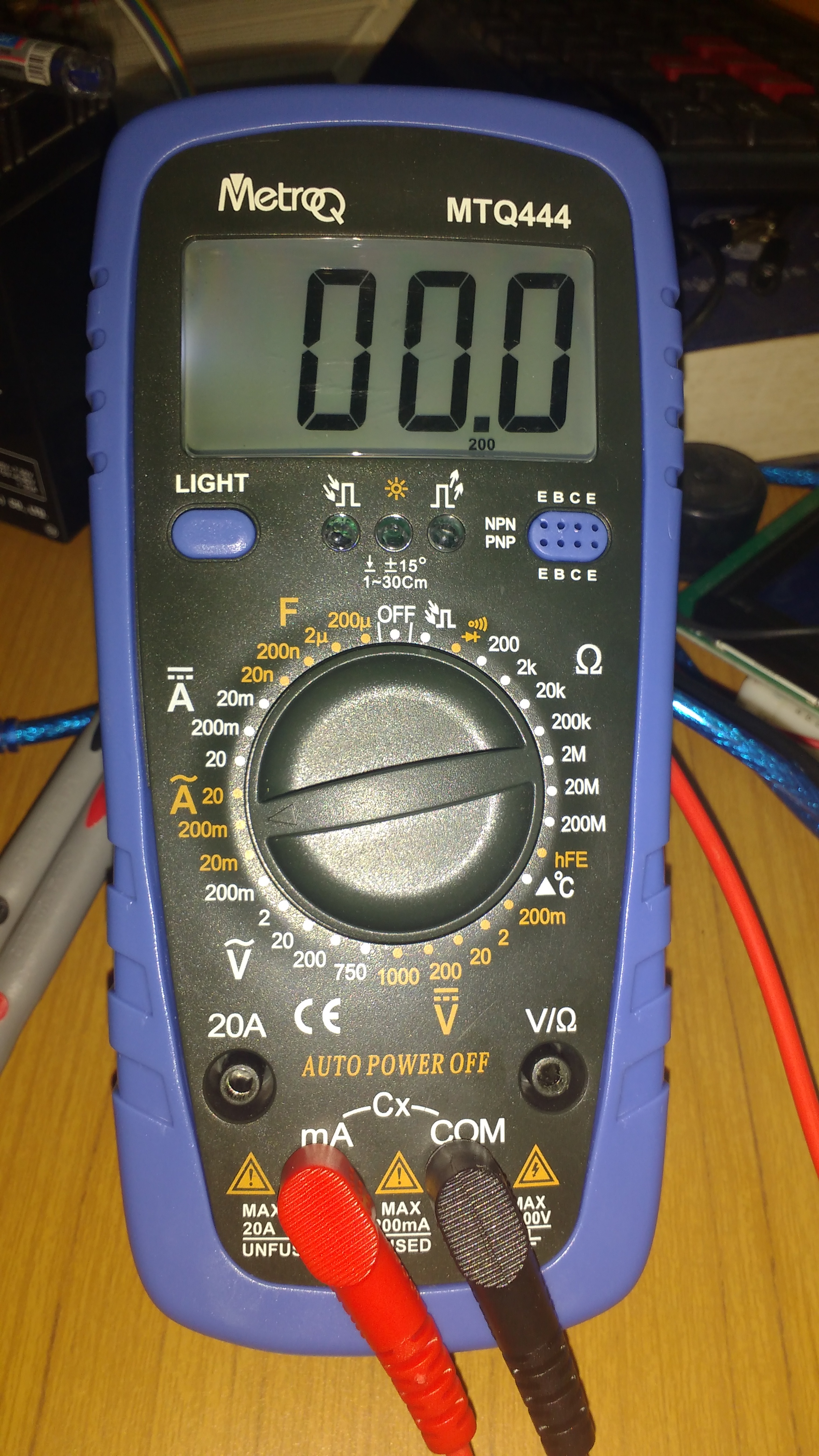
But when i measure through my DMM again it is 0. I am using MTQ444 metroq DMM. I have attached the image of DMM and mode which i set to measure.
Let me tell you my confusion. I have connected red probe to one end and COM probe to other end of CT’s tip and sleeve. Tested with burden resistor and without burden resistor. But i am getting 0 only. What i am doing wrong? Am i connecting properly? since it is current output transformer i guess i can measure current. but i can’t.
I don’t know your multimeter, but the picture shows it on the 200 mA range. You’ve got 1.45 At (ampere-turns) in your c.t., that should give a secondary current of 725 μA (0.725 mA). You should be able to measure that - without the burden resistor of course (the ammeter is the burden). Your meter has an internal fuse to protect it, it says on the front. Check the fuse.
Thank you Robert. First I am happy that i am measuring it in right way.
I checked the fuse and its good. Also i just did a small test of hooking one of the wire to the circuit with ammeter probe in AC current mode. so in disconnected circuit i get erroneous value around 143.85 but in connected line with Ammeter it says 0.09 or 0.08 which is correct. So I guess fuse is working. Am i Right?
if its not right is there any other method to check whether AC current mode working or not?
If you get any indication, the fuse is probably good.
I’m not sure what you are measuring there.
If you disconnect your c.t from everything and connect just your ammeter on the 20 mA a.c. range to tip and sleeve of the c.t’s plug, you should read about 0.725 mA (as closely as your meter can indicate of course) with the lamp connected and 10 turns through the c.t.
The problem is setting the ammeter to 20mA AC range. When i disconnect CT from everything and i can read 0.68mA from DMM and with burden resistor alone i am getting 0.48mA. Also with all the circuit connection and measuring current between tip and sleeve gives the same 0.48mA.
Thanks again Robert. Now i have to go back to origin of why it is giving 0.725mA in Arduino and 0.680mA in DMM. Is that difference of error is common? or we can fix it?
No, I’ve just been doing electrical engineering for about the last 50 years, and earning my living at it for most of that time.
You are working below the specified minimum current for your c.t. According to the data sheet, it is specified as “Non-linearity ±3% (10%—120% of rated input current)”. So the accuracy is not specified below 10 A. If you study the theory of c.t’s, you’ll see that the accuracy inherently falls as the current gets smaller - this is because it has to draw power from the circuit it is measuring to magnetise the core - and supply the core losses. There’s nothing you can do about that, other than fool it into thinking that it is measuring a larger current, which as you now know, you do by having a multi-turn primary winding.
So other than that, there is not much you can do. The best way of course is to choose a c.t. that is designed for the current range you want to measure - and there are few that are capable of driving the 1.6 V rms that an Arduino, or the 1.1 V rms that an emonTx needs, so the choice is limited.