I’m looking to purchase a Solar PV bundle to monitor generation, import and site consumption. I have looked at the guide and I’m struggling to relate it to my own setup I think due to the lack of colour coding of all the cables between the solar and the consumer unit. I believe I would need to set this up as a Type 2 installation from the guide to achieve what I’m looking for. Could anyone please advise if the solar PV bundle would work for me given the below setup and if so where I would position my CT clamps?
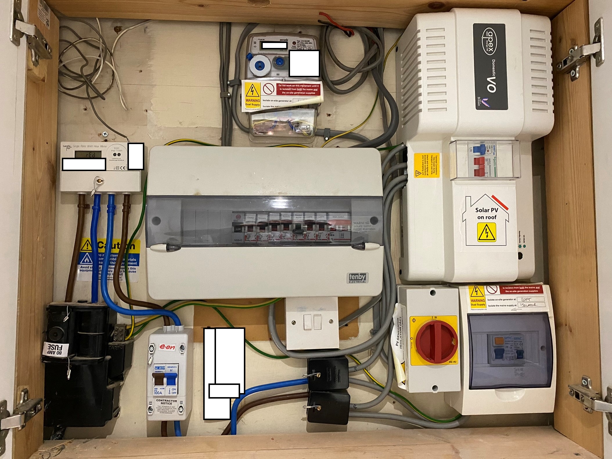
I have attached a picture of what I have in the meter box and have blanked out things like the MPAN/serial numbers etc.
No, that’s actually a “Type 1” set-up, and the Solar bundle should be OK for your needs.
CT1 goes on the House supply, which is the grey wire “4” coming out of the Henley Block (the black one) where a brown wire goes in and that and another grey wire comes out. A check would be to see where “4” goes - it looks as if it goes to that voltage regulator device and that supplies the rest your house.
CT2 goes on the PV infeed, which is the grey wire that isn’t wire 4, that comes out of the same Henley Block and goes into the PV Isolator and RCD in the 2-way consumer unit housing bottom right.
Because of that voltage regulator device, the voltage that your PV sees will be different to the voltage the rest of the house sees, so for accurate readings the a.c. adapter of your emonPi needs a socket on the supply side of that voltage regulator. The emonPi power (via the 5 V d.c. adapter) can use any convenient socket.
Firstly thanks for the fast reply and advice on the CT placement that’s much less complicated than I was making it.
I don’t think I have a socket on the supply side of the voltage regulator as all the sockets will be connected to the consumer unit I believe and therefore be “regulated”.
Does this mean I can’t get an accurate read of generation due to the voltage regulator device changing the voltages or is there another workaround I can use? If the AC sensor was put on the regulated circuit what percentage of accuracy would I lose approximately?
Sorry for all the questions I’m just admittedly fairly ignorant of the complexities of what’s involved.
That’s exactly what will happen - plus there might well be a phase shift due to the regulator too that will cause further errors.
How long is your piece of string?
That’s anyone’s guess. If the PV is feeding in at the legal maximum of 254 V and your house is regulated at 220 V and you’ve not got a phase shift introduced by the regulator, then it’s out by 256/220, or 16%. I wouldn’t expect that to happen often, but it could.
I can’t accept these claims in the documentation I’ve looked at:
All domestic electrical equipment is designed to work within a range of 207V and
253V if it complies with European Conformity CE But, critically; the optimum and most
efficient supply voltage for these appliances is 220V.
When the supply voltage exceeds 220V wasted power can be generated, as both
heat and vibration; this could significantly reduce the life span and efficiency of the
equipment.
If anything you own was designed in the UK and before the UK joined the EU, it will be designed for 240 V ± 6%, so running that at 220 V might use less energy but it could actually decrease the efficiency of the appliance.
I can see that you haven’t. If there’s room for another MCB in the box bottom right, you could add a 6 A MCB (that’s plenty, but you could use a 16 A) in there and feed a double socket designated for the emonPi only, one for the d.c. power and one for the a.c. adapter.
Not so much “correct” the issue, but remove the source of the problem.
Why did you get that regulator in the first place? Generally speaking, devices like that reduce the power that an appliance uses, but they will only reduce the energy if you didn’t need that much in the first place. E.g., if you’re heating a kettle of water and it trips off when steam is generated, it will take exactly the same amount of energy to boil the water, no matter what the voltage. At a reduced voltage, there’s less power so it just takes longer. If it’s (say) lighting that’s on for a fixed time, then it will possibly save energy because the light is less bright. However, if it’s a computer with a regulated power supply, that will just draw more current at the reduced voltage, and the power and energy will both be exactly the same whatever the voltage.
Well, I don’t have one, and I’d only contemplate one if I had severe voltage fluctuations. If your inverter can display the voltage, it might be worth keeping an eye on that, to check just how much it does change (and if it can store max and min, so much the better).
Here’s what my voltage looks like, over the last 7 days. (Don’t take the actual values as being accurate, it’s probably not calibrated as I’m testing the radio.):
If I can read solar generation direct from the inverter itself would that resolve the issue or would the voltage optimiser also affect the consumption reading accuracy?
That should remove the main source of the error in calculating the PV generation part.
Or, you might be able to use the flashing LED on the generation meter itself. The image isn’t quite sharp, it looks like 3300 pulses per kWh? That won’t give you the “keep-alive” power drawn by the inverter while it’s dark, but that should be only a few watts anyway.
If you’re going to do that, it will be a good idea to move the c.t. that you were going to put on wire 4 onto the line conductor coming out of the voltage controller and going into your consumer unit. It going to be one of the two passing between the Henley block and the 2-gang switch, but I’ve no means of knowing which. It doesn’t actually matter, but the c.t. should face the opposite way if it’s on the neutral compared to the line. That way, you’ll avoid any phase shift that the voltage controller might introduce, but you’ll also miss the power dissipated (as heat) by the voltage controller. You can estimate that by feeling the temperature it runs at.