Perhaps it is possible (if the Tesla Gateway uses a c.t.) to combine that c.t. with another around the dump load spur as you suggest here ![]()
We know that Ben has some twisted pairs in CAT6 cable available to extend c.t.s between garage and house.
Perhaps it is possible (if the Tesla Gateway uses a c.t.) to combine that c.t. with another around the dump load spur as you suggest here ![]()
We know that Ben has some twisted pairs in CAT6 cable available to extend c.t.s between garage and house.
I keep coming back to my original question - with a battery in the equation, that can act as a buffer for an extra PV (by charging) or extra load (by discharging), is there much need for a diverter?
I can see that with the right wiring you could definitely still use a PV router, but even in this scenario is there much benefit? Assuming the battery can regulate itself quick enough to minimise import/export.
You thought there was before the Gateway appeared, what you’re really asking is, what happens if I don’t have it? I think this turns into “Is my battery big enough to absorb enough of the P.V. so that it will support all the normal stuff in the house and the immersion heater if it’s on a thermostat / time clock or whatever?”
Agreed, that is what is boils down to. And since turning off my PV diverter I think the answer is “Yes” in my case. Particularly once I add some basic automation rules over the top, where I only turn on the HWC load if the battery > 80% and solar generation > 3kW.
I really do appreciate your expert opinions and insights @Robert.Wall and @dmajwool. I think I am happy I have considered all the options and am not missing anything.
I hope this thread is useful to someone else in my position with similar questions ![]()
I asked myself the same question when I added a battery to the system, but I’m pleased I kept it and the Mk2router remains a useful part of my total system.
All valid points, but in my situation it just doesn’t work effectively unfortunately, thanks to my wiring topology.
I wish I had cottoned onto this nuance earlier so I could have run some extra flex cables between the garage/house, so I could isolate the diverter dump loads from the gateway.
But that would introduce another issue, if my grid connection went down and the gateway switched to battery backup, I would not have power for my HWC.
Although that could be solved thanks to having 2x elements in my HWC (middle and bottom). The middle one could be “inside” the gateway and not part of the diverter load, the lower one would be the diverter load and not part of battery backup.
I will know for the next time I build a new house ![]()
Hi Ben,
This is only a discussion. Our work is done if you’ve appreciated that your power wiring topology is OK as it is, and you could achieve a different diverter result by running the c.t. clamps in a novel way using cores of your cat6 cabling running between garage and house.
Cheers, David.
So in order for this to work in my situation, I would need a CT clamp around the HWC element spur, which is fed back to the PV router over a spare CAT6 cable. That remote CT would then need to be plugged into the PV router and the firmware customised to subtract that reading from the grid CT readings.
Do I have that correct?
Not quite. The suggestion is to change the wiring of the Gateway’s c.t.
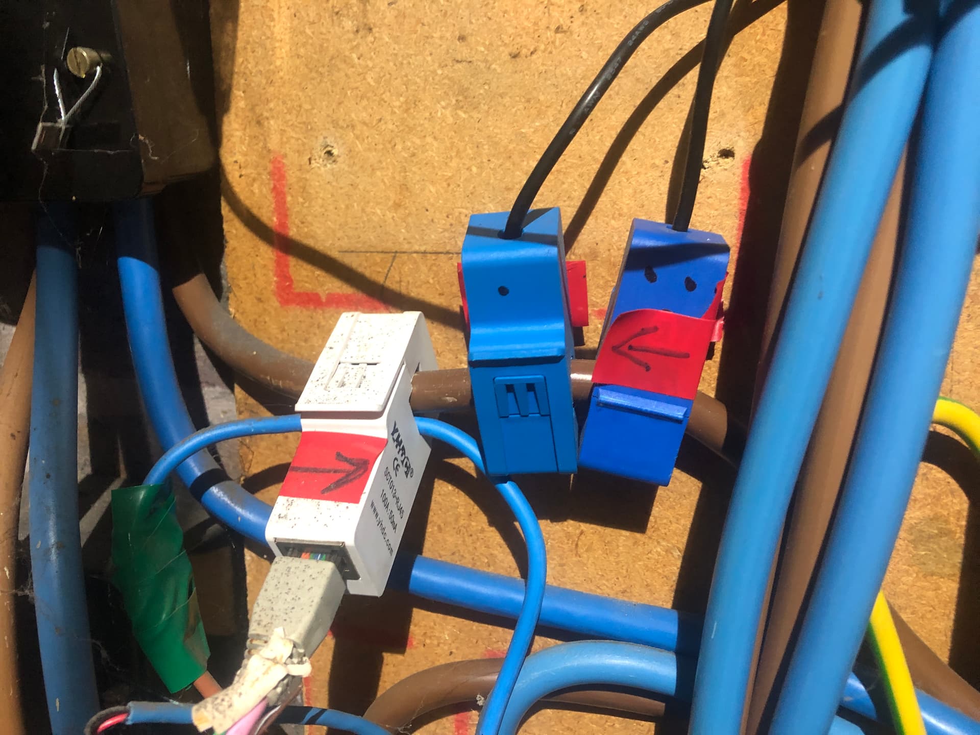
Here’s my brown grid incoming live cable. My Battery’s grid c.t. is on the left and the Mk2’s grid c.t is on the right.
The additional cable running through the battery’s c.t. is the supply to the Mk2.
If I’ve got things clear in my head, the logic here is:
Your present situation:
The solution that worked for me
As Robert said,
The effect of this is
I don’t know if the Tesla Gateway has an accessible c.t. that can be tampered with in the same way that my battery does. But if it does, I think you could try fitting a c.t. around the immersion heater spur and extending it out to the gateway’s c.t.wiring and combining them as discussed here
Or you might think the work outweighs the benefits ![]()
I think that is where I am landing ![]() .
.
But I am glad to have gone thru this process with you two, I have learnt a lot and feel like I understand the system better than before.
I certainly didn’t realise you can wire two CTs in parallel in order to net their readings against each other!
With care! They must be both genuine current-output and the same ratio. This works because they are current sources, and wired in parallel the currents add.
If they are voltage-output type, both must be the same output voltage for the same rated current, and they are wired in series because they are voltage sources, and wired in series the voltages add.
You must calculate the value of the total current and size the burden accordingly; or ensure the sum of the output voltages doesn’t exceed the input voltage.
If they face in opposite directions, the currents/voltages subtract.
Or you can have a current-output c.t. with its own burden and it becomes a voltage, which you then wire in series.