Can you do a single-line diagram (like mine) showing what you have.
I can’t do much immediately, my OS update failed and I’m using a phone to post this.
Can you do a single-line diagram (like mine) showing what you have.
I can’t do much immediately, my OS update failed and I’m using a phone to post this.
Sorry, I am not setup for fancy diagrams so I had to hand draw it :).
The Powerwall and Gateway are effectively “the battery”, and the physical wiring is a bit different, in that the grid feeds into the gateway, along with the battery and the inverter, and then the house is a load out the back of it - i.e. the gateway controls everything - but in terms of the logical flow this digram is the best match with how you laid yours out above.
…But you’ve left out where the powerwall & gateway connect power-wise, in relation to where the immersion heater feed is?
(I’m thinking is it possible to trick one of the systems, like feeding the immersion current backwards through the powerwall c.t. to subtract (i.e. remove it), or vice-versa with the powerwall feed and the router c.t.)
And can you restate your objective – primarily, is it hot water or a charged powerwall?
I don’t mind that - I wanted a clear diagram showing the essentials - where the power flows and where the controls are. Neutral returns and safety earths play no part when you’re looking it this type of problem.
Hopefully this is clearer - basically everything connects into the gateway, and that has all the “smarts” and relays for disconnecting the grid in the event of a grid outage (to protect the linesmen), and diverting excess solar to the battery etc.
The HWC is part of the house load, behind the gateway, along with everything else.
My goal is to disable the PV router until the Powerwall is charge to 80%, and then to divert any excess to the HWC.
I have a flow in NodeRED which monitors the Powerwall SOC, only enabling the PV router when it gets above 80%. But the problem is that once the HWC starts heating it will draw the full 3kW because even if there is only 1kW of excess solar, the battery will topup the rest before the PV router notices.
The other thing to note is that the Gateway, Powerwall and Inverter are located in my garage. There is then a feed to a second D/B inside the house where all the loads are connected, including the HWC. So there is no way to “trick” the Powerwall unfortunately.
Trying to reconcile the words and the picture, your grid infeed comes onto your premises, into the house, and goes via the Mk2PVRouter c.t. out to the garage and the gateway, then back into the house?
Or should you have drawn the gateway not ‘in-line’ with what I would term the “original direct line” feed from the grid via the meter to the house consumer unit, instead as a branch connecting to the direct line just downstream of the Mk2 c.t. and the supplier’s meter.
The PV router lives in the garage next to the Gateway. The CT clamp from the PV router is around the ‘original direct line’ from the grid/meter, before the Gateway. The grid feed arrives onto the premises in the garage.
I think the confusion is over how the PV router controls the HWC load - I should have made that more obvious sorry. The PV router sends MQTT messages over my home LAN network. The SSR controlling the HWC element is driven by a second Arduino device, which listens for these MQTT messages, and switches the load accordingly.
Hence the dotted line from the PV router to the HWC load switch, is over my LAN and not a direct connection.
I see now. Let me think about this.
Hi Ben,
How would it be if you rewired the output of the PV router and attached it directly to the feed into the HW element. I.e. after your switch.
And then you can use your fancy Arduino SoC 80% conditional switching to close the switch on the diagram.
Then, when below 80% you just feed Mk2PV output to the heater, and above 80% you get both Mk2PV and gateway.
I have something similar here and don’t have an issue with mashing together raw mains and Mk2PV output together.
My battery often leaks a bit of energy back towards the grid (it’s hard to keep at exactly zero), and the Mk2PV router mops this up and diverts it to the DHW.
Hi David,
Not sure I follow. There is a dotted line from the PV router to the HWC feed switch - it probably isn’t that obvious sorry! So the PV router is controlling that switch and as I started exporting to the grid, it will start turning on the HWC element to soak up any excess.
The problem is that once the HWC element is turned on, the Gateway will see that extra load and if there is not enough solar to cover it, will begin discharging the battery to cover any excess needed.
This means the PV router never “sees” the scenario when the HWC load is greater than the available excess solar, and hence never turns off the load, unless the battery is completely depleted.
Would be keen to hear how you are using your PV router with a battery tho.
Cheers,
Ben
Hi Ben, I see. Sorry, it was me who didn’t grasp what the dotted line represented. Happy to share what I’m doing, but for the moment let’s think about yours…
You say the battery and Mk2PV router are in the garage (and presumably the HW tank is inside the house). What distances and cable access routes are there between the GW and the house distro board?
I think you could make a “normal” Mk2 circuit by adding one more cable.
This cable could be either for 3kW mains or a c.t. extension (eg. cat5) - dependent on whether you move the PV router next to the HW tank spur.
I’ll wait and see how @dmajwool’s proposal works before I do any more.
Hey David,
Unfortunately the house is passive, so has an air tight membrane around the outside. The garage is outside of the thermal envelope so I have run various CAT6 and power cables from the garage to inside the house, and then sealed them all up where they pass thru that membrane.
In other words, it is not possible to run additional cables between the two locations :(.
I have been testing the system over the last few days, without the PV router enabled. I have just added a crude form of diversion using a NodeRED flow which checks the Powerwall SOC and solar generation every minute. If > 80% SOC and > 3kW of solar being generated, turn on the HWC element, off otherwise.
The HWC element draws 3kW so assuming solar export is just 3kW it will cover the HWC and the house load will be covered by the battery. If the battery drops below 80% the HWC is turned off, and any excess solar is used to charge the battery again.
This system appears to be working quite nicely. The battery is used as a buffer and ensures we never pull anything from the grid.
I am still using the Arduino with the SSR to control the HWC load, but it is not being driven by any fast PV diversion logic.
This means I can remove the PV router from the garage and recommission it inside as a standard 4x channel energy monitor (EmonTX) for monitoring 4x additional circuits inside the house.
Personally I am pretty happy with this setup now. It has fewer “moving parts”, but still ensures I soak up any exceess PV without ever importing from the grid. It is very easy to tweak the battery/solar thresholds in NodeRED if I need to.
I came here to ask you clever chaps if anyone had tried this kind of setup, using a battery instead of the PV router. It seemed like a good idea but I am no expert and wanted to see if anyone else had tried it or if there was anything I was missing!
I really do appreciate your feedback and insights!
I would never consider that a misfortune!
Does one of these cat6 cables run from the Mk2 into the house? If so, could we move things around and use 1 pair of that cat6 to extend the Mk2’s grid clamp so that the Mk2 can go somewhere on the HW tank’s spur.
If we then temporarily disable all your 80% SoC smarts and load a basic sketch into the Mk2, we could connect the 240v inputs and outputs of the Mk2 in parallel with your switch.
I reckon that, irrespective of the battery SoC, whenever there is grid feed-in the Mk2 will start diverting into the HW tank.
If your other switch is open circuit, the energy sent to the tank will be capped by the Mk2 such that grid=0 watts.
If you close your other switch, the HW element can draw whatever power it likes, uncapped by the Mk2.
Do you know if your battery “leaks” into the grid? My battery is set such that it attempts to maintain the grid feed at 0 watts. But what I find is that this is not 100% achieved and I typically import about 0.8kWh/day on a sunny day when I have plenty of solar and battery. This isn’t a big deal but it is irksome.
I find that the battery has a response time of a second or so when a load changes abruptly. Without a diverter this exhibits as frequent small imports and exports.
I find the Mk2PV router is excellent at trapping those exports and routing them into the Hot Water tank.
It’d be nice to think that the above wiring topology also addresses this in your situation as well as it does in mine.
Indeed, after re-reading that I realise it wasn’t the meaning I intended!
Not that I have noticed. I have found the Powerwall is pretty responsive to shifting loads. My energy supplier has a pretty nice visualisation of my usage (black is 0kWh);
My off-peak rates are between 9pm - 7am so you can see the battery is doing a pretty good job over the last month (which is late winter/early spring here).
I do potentially have a spare CAT6 cable I could re-purpose for this. But I am not sure I see how it would help. The HWC load would still be “inside” or “behind” the Powerwall Gateway, so it is going to see that load when it is on, and switch to battery if there isn’t enough solar to cover it.
I think I need that HWC spur to be before the Gateway in order for the PV router to work properly… I think…
Moving the PV router next to the HWC doesn’t change anything I don’t think. Because I am using MQTT/LAN to control the HWC load (via a SSR) they are “virtually” next to each other. The PV router sends divert on/off signals to the SSR over MQTT, but it is in effect directly controlling the HWC load and can switch it fast enough to balance things out.
If I could re-route the HWC spur into the garage and wire it into the switchboard “before” the Gateway, i.e. between the grid/meter and the Gateway, I think it would then make a difference and allow the PV router to accurately soak up any excess being exported to the grid.
Hi Ben,
Lets strip this back a bit. Take another look at Mk2PVRouter - Introduction
In the block diagram
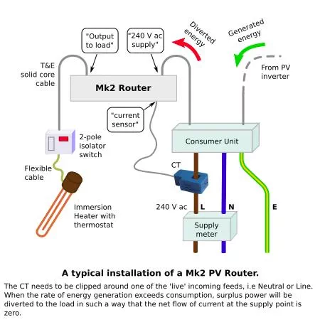
Consider that the “consumer unit” block is your Powerwall Gateway and that your battery is 100% full and the sun is shining.
Also consider that the Mk2router is inside your house adjacent to your existing smart switch and wired in parallel to it (so that when closed the smart switch bypasses the Mk2router).
In this scenario, your PV inverter will be sending power to the Gateway which will then be flowing out to the grid.
My Mk2router doesn’t have any nodered, mqtt or any such stuff. It is entirely stand-alone. It has a grid c.t., an Arduino sketch and a solid state power gate that opens and closes, conditional on the grid c.t.
The 240 volt supply wiring route into the Mk2 does not matter. Anywhere inside your gateway is fine. All that matters is that the c.t. registers some grid export and then the Mk2 increases the duty cycle of its gate (delivering energy to the load) and the grid c.t. sees correspondingly less export until a balance is found and your grid export reduces towards zero. (unless the water is already hot or if you have more than 3kW excess etc etc)
When the c.t. detects import from the grid (ie when the battery is charging from the grid), the Mk2 gate stays open circuit.
The battery is not connected directly to the HW heater so there is no reason why the battery will runaway and supply maximum power to the HW heater. The battery is connected to two switches in parallel - the Mk2 and your smart switch. The Mk2 switch will only activate when energy is flowing out to the grid, and your parallel switch will do whatever some other device (your finger?) instructs. So you can program some timer or SoC dependent water heating into this smart switch.
When wired up like this (as I have), the battery has first call on the PV energy. It will charge the battery before diverting excess to water heating. This is not entirely efficient because of battery round-trip losses. In my battery there is a register to limit the charge amps. When the season allows, I set this to a lower figure in order to force some export which will then be picked up by the Mk2. We find this convenient because the water is heated earlier in the day.
Hi David,
I am thoroughly enjoying this discussion by the way! Thanks for taking the time!!
I think there is still some misunderstanding about my setup. I wish I was better at drawing so I could map it out more clearly.
My PV router is physically located in the garage, with a CT clamp around the grid feed, between the supply meter and the gateway. So it is correctly measuring the grid import/export, as in the diagram above.
The PV router is also directly controlling the power to the HWC, albeit via virtual connection over MQTT/LAN. The net effect however, is that as the PV router detects export to the grid, it will switch the HWC element on/off at a rate that brings the export back to zero. This all works and I have been using this system for years in my previous house, with no gateway/battery.
My PV router is the same as yours, standalone. It has custom firmware to send the load on/off commands over MQTT rather than switching a relay directly via a GPIO pin, but again, the net effect is the same. It is directly controlling the delivery of power to the diverter load, my HWC element.
It also has the ability for me to disable the diverter, via an incoming MQTT message. So I can tell the PV diverter to stop trying to divert if I wish. This doesn’t do anything other than prevent the divert on/off signals from being sent.
So aside from that, the PV router is very much like the diagram above, identical in fact.
So the PV router will turn on the HWC when it detects export to the grid - i.e. when the battery is charged and there is solar being generated, but also when there is a rapid change in load in the house and the battery might take a second to react meaning there is a small amount of export as it re-balances itself.
When this happens the HWC element turns on and starts drawing 3kW. If the solar generation is only 2kW and the house is using 1kW then there is a 2kW shortfall. At this point, assuming we are in the peak rate tariff (i.e. day rate), the gateway will try to avoid any import and start discharging the battery to cover that shortfall.
The PV router CT clamp sees the grid feed return to zero, since the battery has now taken over, but it doesn’t see it start importing, therefore it never sends the OFF signal to the HWC load. It is happy that the diverter load is perfectly balancing out the grid feed to zero.
So, because the diverter load sits behind the gateway, once the PV diverter is triggered by any kind of grid export, that load will remain triggered until the battery is depleted enough for the gateway to start pulling from the grid (or if there is a rapid load change in the house which causes a short spike of import), which the PV diverter will see and then shutoff the load.
As per Roberts original diagram above, if the diverter load was “before” the gateway, then the gateway would never “see” that load and the battery would never be used. Thus the diverter would be able to happily switch the load as required to ensure anything coming “out” of the gateway, and destined for the grid, can be soaked up before being exported.
This whole process has been very useful for me, writing these sorts of things down always helps get a clear picture in my mind of what is going on!!
Going back to what I wrote in Post No.18, the problem is that Gateway was never designed to be part of a bigger system – one incorporating the Mk2 PV Router. Neither was the Mk2. What you have are two control systems each forming what we call a ‘closed loop’ - meaning the system monitors the result of its actions and modifies that action accordingly. What you (@ben.jones12) have --and you’ve realised this – is two control loops that are intertwined.
My thinking is turning to asking what information do you have or can find out by inspection about the internals of the Gateway? Is it possible to reroute cables and locate the Mk2 c.t. inside, maybe adding or subtracting currents by passing wires in different directions through the c.t. so that it sees a current that will give it the information it needs. Can you do what @dmajwool did in 2019?
You also mention that the Mk2 responds much quicker than the Gateway (as it’s designed to do), so would holding off its response in order to give the Gateway time to pick up or dump its load (to or from the battery) solve the problem – but at the cost of a few seconds of imported or exported power?
Thank you Robert.
Ben’s latest post reminded me that you helped me with some wiring tweaks to avoid my battery getting into the same kind of loop where it supplies more and more power to the dump load.
Our solution was to give the battery’s grid c.t. a sniff of what the dump load was receiving, as discussed in the 2019 thread.
In Ben’s situation this may be more difficult to achieve because of the separation between the dump load and the grid monitoring point. But in addition to the 2019 post you quote, there is also a post in 2023 where we discuss using multiple physically distant c.t.s to aggregate a value. And that might be a good approach in Ben’s situation. aggregating multiple c.t.s
No we didn’t - we removed the current the dump load was using from the total the grid c.t was seeing by running the cable carrying that current backwards through the c.t. – subtracting it from the total.
But we know @ben.jones12 can’t do this because of the topology, so we’ve got to work out an alternative - maybe add or subtract something from the Mk2 c.t?
Sorry, you are quite right. Just my lazy writing.


