Hi I’m a newbie on this forum, but I have had a ‘Robin Mk2’ diverter since 2013.
Will my diverter function with a smart meter? I’m asking do that I know the situation for when/if I’m forced down the smart meter route. Thanks
In short, we don’t know.
The diverter will continue to work of course, but the real question is, will you get charged for every tiny chunk of energy you import, because the meter’s “energy bucket” is too small for the matching chunk you export to cancel it? It depends on exactly how the meter is configured internally. I’m afraid the only answer is to wait and see. My suspicion is you will get charged, possibly for all of each small chunk of import. But you should not be charged for your export.
The safest way to operate a Mk2 PV Router is in its “Normal” mode, rather than “Anti-flicker”. Normal mode is the default setting for most of the sketches on the Downloads page at https://mk2pvrouter.co.uk/downloads.html. The original Mk2 sketches as available from the archived OEM forum are no longer supported by me.
A smart meter has recently been fitted at my own house. Although there are still 1000 optical pulses per kWh, some of the LEDs on the meter blink when the Mk2 is running its original “Anti-Flicker” configuration. When switched to its “Normal” mode, all LED activity ceases and I feel confident that no charges are being incurred.
Tightening the AF settings could well have a similar effect but I have not yet done so.
Hi Robin
My mk11 was built to your design for me by a member of the now defunct ‘Talking Solar Forum’. I don’t really understand what you mean by the different modes of operation. Can you explain it to me please?
Thanks
Chas Hyde
From the comment near the top of the basic Mk2_bothDisplays_4.ino sketch:
The power-diversion logic can operate in either of two modes:
- NORMAL, where the load switches rapidly on/off to maintain a constant energy level.
- ANTI_FLICKER, whereby the repetition rate is reduced to avoid rapid fluctuations
of the local mains voltage.The output mode is determined in realtime via a selector switch.
When there is a constant surplus of power (that is less than the dump load draws when it’s on continuously), then as you know, the diverter switches the load on and off so that the average energy dumped exactly matches the surplus being generated.
There are two ways to do this, slowly or quickly. “Normal” mode is where the load is switched rapidly, “anti-flicker” is where the load is switched slowly. In both cases the ratio of on-time to off-time remains the same, it’s the size of that chunk of energy, therefore the absolute length of time it spends in the ‘on’ states, and in the ‘off’ states, that changes.
If the meter reacts to very small chunks energy, the diverter must switch rapidly so that the chunk of energy flowing in through the meter while the dump load is on (and that’s equal to the chunk that’s flowing out when it’s off) is small too - smaller than the meter’s. Otherwise the meter triggers, the LEDs flash and you get charged.
As your diverter was built for you, do you know the details of which version of PCB and which sketch you are using, and if it’s been changed in any way?
Sorry, but no. I thought diy was beyond me so allowed someone to build it for me.
Is there a switch labelled “Mode” on the outside? That’s part of the kit, but in their wisdom the builder might not have fitted it, or might not have labelled it.
If not, are you able to contact the builder to ask them, or are you up to taking the cover off and looking inside?
A couple of warnings if you do decide to look inside:
1. There are live parts inside, so isolate the mains first,
2. If there are LEDs, switches, the display or anything else fixed to the lid, there will be wires connecting those to the base and the circuit boards. Don’t pull them and break them off. When you put the lid back, don’t trap any wires.
What you will be looking for are two places for a wire to be soldered or two thin pins 0.1" apart, on the board very close by will be the label “mode”.
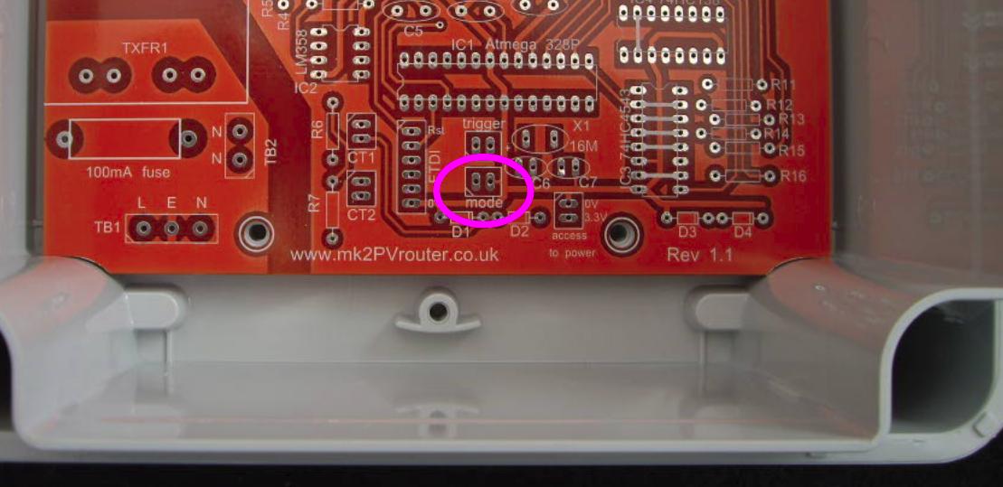
If there’s nothing connected there, it’s very likely that yours is operating in “normal” mode (not proven however, they could have changed the sketch). If there’s a small (5 mm wide) plastic covered link, or a piece of wire, there, it’s probably in “anti-flicker” mode.
If you’re unsure, take a close-up photo of that area and post it here so that Robin or I can take a look.
Hi Chas,
I agree with all the advice that Robert Wall has provided. Does your system use one of my own PCBs as shown above, or does it use an emonTx?
When your Mk2 Router is diverting surplus power on a sunny day, the way that it is operating should be apparent from the rate of its on/off transitions. If these transitions are too fast to count, it’s in “Normal” mode. But if it’s cycling on/off every second or two, it’s in “Anti Flicker” mode.