Living in Japan (with split-phase similar to North America) and trying to setup a smartEV charger using an emonpi and OpenEVSE.
-
If I am only interested in monitoring import/export from the grid (not how much solar I am making), do I need the emonPi solar option with a CT to monitor solar generation from the inverter? I mean- can I simply use 2 CTs on my mains to monitor if buying or selling (does the CT monitor which direction the current is flowing)?
-
If I do need the CTs on the solar to monitor import/export, then limited to the 2 CT inputs on the emonpi. From what I read on the ‘Use on North America’ page, I need to parallel 2 CTs for the mains (split phase) and use (maybe) 1 CT for the solar.
-
If #2 is my option, then the easiest to understand setup is at:
https://community.openenergymonitor.org/uploads/default/optimized/2X/b/b21a65e45a094cadd17df58d763351594c646ddc_2_690x388.jpeg
BUT, I searched quite a bit and unable to find a 100A:0.5V split core current transformer.
Can anyone recommend which CTs to use for the mains for a split phase system. Hopefully a pair of CTs that may not need to be calibrated and/or modified (burden
***************Useful post from Thomas Dunbar ***********
I used an EmonPi and three CTs. (two WC3-100-MV500 and one WC1-025-RV001)
For grid sensing, I used two 100A:0.5V Wattcore split core current transformers. I installed them per Figure 3a and connected them per Figure 5C on the “use in North America” page linked to earlier.
- This may also be an issue. Is this something I need to check?
***************From same post from Thomas Dunbar ***********
“When I ordered by EmonPi, I said I didn’t need the default CT and in return, they removed the surface mount resistors”
Welcome, Paul, to the OEM forum.
The “bundles”, e.g. the solar option, are just that. If you’re not interested in knowing the contribution from the P.V., you can indeed use the two c.t’s on your two incoming feeds, and provided you also have the a.c. adapter, you can determine the direction of power flow.
That is the other way to do it. You lose the ability to know the contribution of the two incomers separately, you gain the ability to know the P.V. input.
This is one reason why we are moving to 0.333 V output c.t’s for the emonTx V4. C.T’s that are capable of 1 V or 1.1 V output with or without an internal burden are hard to find.
Another option for the P.V. infeed might be to count pulses, if you have a generation meter with a pulse output - optical or S0. That’s not an option for your main supply, because generally you get no usable indication when exporting energy.
And yet another - if your generation meter has a data output that’s usable, that can be sent to the emonPi, but it will require an interface to connect to a USB input on the emonPi.
If you have c.t’s with an inbuilt burden, i.e. the output is quoted as a voltage, then you must NOT have the burden inside the emonPi. The Shop is always open to negotiation, so they can remove the burden resistors if you ask. There are also holes to replace with wire-ended resistors of a different value, should that be needed. If asked, The Shop might be able to do this for you.
Thank you for the advice. I used the 2 CTs that came with the emonpi from the shop and connected to CT1 and CT2 inputs on the emonpi. Appears to be working fine for checking import/export.
I initially set the emonhub.conf to 100 V as Japan is 100 V but realized this is a switch setting, not the actual voltage.
After setting too 110V, all worked OK.
emonhub.conf calibration=110v
So I am guessing that the USA AC-AC Adapter (for 120V) works OK in Japan with 100V outlet.
Next is to set up the EVSE charger.
To monitor solar generation, seems it will be easier to use the EmonTX (when the latest version is out.) rather than the emonpi. The emonTX has 4 CT inputs, so I can use 2 for the solar and 2 for the mains (split-phase) I hope.
Yes, that should be OK.
If you’re using the emonTx V3.4, No.4 c.t. has a different burden (120 Ω) so it’s derated to 16 A when used with the YHDC SCT-013-000. You can convert it by adding 27Ω in parallel with the 120 Ω burden on the pcb.
The emonTx V4 will have 6 inputs, BUT these aren’t directly compatible with your YHDC c.t’s (yes, I know, but it’s better in the long run). You’ll need a separate burden (6.66 Ω, 0.1 W, or 3×20 Ω in parallel) to convert the 50 mA output of a YHDC c.t. to 0.333 V. You could use the emonPi on one pair and an emonTx on the other - the potential problem is the readings won’t be synchronous, so the sum or difference won’t necessarily be correct.
Thanks. I’ll order the emonTx v.4 when it becomes available. Will purchase new CTs that are shipping with the emonTx v.4 so I don’t have to worry about making any changes to the hardware/software (do-able, but a bit of a learning curve).
Next task is to get my emonPi working with the OpenEVSE WiFi EV Charging Station so I can charge my EV with 100% solar! Fun stuff.
Thanks for all of the support so far. It is exciting for 1st time users! Seems the emonTx v4 may not be available for a bit, so trying again to get my emonpi set up with 3 CTs-- 2 CTs in parallel to measure the mains (split phase) and 1 to measure the solar generation. The GOAL is to get my EV to charge with solar only using OpenEVSE and emonpi.
Still unable to find CTs that will work with split phase. I read the ‘use in N. America page’ carefully and I am following this setup (Fig 5c).
In Fig 5c, the burden voltages are summed; each burden value is calculated to give half of the maximum input voltage for the maximum current. If the CTs are not identical, the burden resistors must be chosen so that they develop the same voltage for the same primary current.
current coefficient = (total CT primary currents) / (total burden voltage)
This arrangement is suitable for ‘voltage output’ CTs, but the output voltage at rated current should be approximately 0.55 V
Question: Is it possible to find a CT with a 0.55 V output?
Or would it be possible to find Cts to satisfy the setup in Fig 5b?
In Fig 5b, the CT currents are summed in a single burden resistor; the burden value is calculated to give half the maximum input voltage for the maximum current either leg. The CTs should have the same current ratio, the calibration coefficient must be calculated knowing the burden voltage at a specified total current:
current coefficient = (total CT primary currents) / (burden voltage)
A ‘voltage output’ CT is not suitable for this connection arrangement.
I am learning step by step, but the fig 5b setup is a bit complicated.
Also checked about the pulse counting, but can’t find a pulse counter easily here in Japan.
What are you looking for? A c.t. for split phase is exactly the same beast as for single or 3 phase. All you are really interested in is the primary current rating, which should be not less than the maximum current you draw on that leg (or really, because you want two the same to make things easy, the maximum current taking both legs into account.
Correct.
Or maybe an easier way to view it: the current that would give you 1.0 V across the combined burdens.
Or 1.1 V across the combined burdens.
It’s the value of the burden that defines the c.t’s output voltage. Remember, a c.t. is inherently a current source - unless you get one with an inbuilt burden, in which case you won’t need a separate burden. So the only thing that matters is the c.t. should be able to develop the 0.55 V. The only way you’ll know is, if you’re lucky, the manufacturer will specify a maximum value for the burden, sometimes called the load resistor.
Possibly easier - you get two identical c.t’s and rate them so that you get not more than 25 mA at the maximum current you want to measure (counting both legs). That way, you don’t need to alter the burden inside your emonPi.
What complicates it for most people is the c.t. is a current source. Everything else you’ve come across - batteries, mains electricity, “wall warts” are voltage sources. If you turn everything you know about voltage sources upside down, you will be close to understanding current sources.
Do you know, or can you make an educated guess, what the maximum current is?
Thank you!. From the emonpi data, 7kw seems to be my max household power (hot water heater & EV charger together @ 200V, plus a few 100V appliances), so I calculate about 35 amps, but to be safe, perhaps 50 amps would be max household current draw.
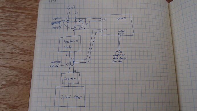
Now I am able to correctly measure my split phase using two of the default SCT013 100A:50mA CTs. But if I want to charge my EV using the OpenEVSE, I think I need to monitor PV generation as well. (I originally thought the I only need to monitor import/export for the openEVSE, but seems I need to monitor PV as well).
Here is my current setup working OK (but with no PV monitoring)
So if anyone can recommend specs for two CTs for the mains (wired in parallel to connect to 1 CT port on emonpi), using the default emonpi internal burden, (
see fig 5B here), that would be quite helpful. The 2nd CT port will be used for PV monitoring to control the OpenEVSE charger.
You could use your two 100 A: 50 mA c.t’s. In parallel, they will give you 50 A on each leg - the only drawback is they will be slightly less accurate at very low currents than two 50 A:25 mA c.t’s.
If you want slightly better accuracy (at a cost), then two SCT023R 100 A : 50 mA would do exactly the same thing.
And of course, as the total current is 50 mA, no changes to your emonPi are necessary.
Extremely helpful advice (and satisfying promoting green energy use)!
I have learned tremendously from the openenergymonitor community. I will organize the information that I have processed into a table (draft below).
Also, if there is a donation process in place, I would like to support openenergymonitor.org.
Thank you again.
The best way to do that is to purchase from The Shop - and recommend the products.
Please don’t put data on 3rd party sites. When that site disappears or the data is removed or becomes unavailable for whatever reason, this topic and it’s content is liable to become largely worthless.
Thanks again. I’m nearly there.
Sorry, if I mis-understood this, if two 100 A: 50 mA CTs are used in parallel, the input is halved (from 100 A to 50 A) on each leg?
Is this the case (no changes to emonpi) for either case?
- two 100 A: 50 mA CTs in parallel
- two 50 A:25 mA CTs in parallel
Yes, that’s correct. C.T’s are current sources. C.T, secondaries in parallel is perfectly O.K. (just as voltage sources in series is perfectly OK - remember I told you to invert everything you know about voltage sources?). Each will contribute a maximum of 25 mA for 50 A mains current, so as the primary windings (= the main cables) are effectively in series, that’s the same 50 A flowing in each leg giving you 25 + 25 mA = 50 mA, the maximum for your emonPi from the two c.t’s secondary windings in parallel.
Again correct - provided that you only run up to 50 A on both legs, or 100 A on one and zero on the other, or 49 A + 51 A and so on - for the 100 A c.t’s.
(And before my colleague Bill from the USA steps in, 100 A on one and nothing on the other will never happen in practice.)
Got it! And thanks for your patience. I marked as ‘solution’ and learned quite a bit. Hopefully this can help others trying to set up a emonpi in split-phase environments. Time to give it a try 
1 Like
Hell, I’ll be the first one to tell you “it ain’t gonna happen!” 
With the way a US residential/commercial load center’s bus bars are built, one would have to work at it to make that happen. They’d have to go to the trouble of installing all of the single pole breakers in every other space which would leave half of the panel empty. Either that, or go to the trouble of finding out which circuits in the building are on which leg and operate only those on one leg.
And… if the panel has one or more dual pole breakers in it, there’s no way it could happen.
2 Likes

