I’ve been contemplating for a while now installing a, to me, comprehensive energy monitoring system
I’ve been thinking I would need 5 emonTX and an emonPi using a self hosted emoncms either on the emonPi or a dedicated server (already have a 24/7 linux box running). I know I’ll need several CT’s, and a few power supplies.
I realize there would be some customization with the node numbers of the TX units.
My current panel setup:
I have one outdoor main panel, that has my meter and a line running to my well house about 75 feet from my house (I live in a rural part of the US), that would need two 20A CTs, then have a 100A split phase line running to my house’s main panel that has 17 circuits, 16 of which need individual current clamps.
Quick ascii panel layout:
Meter panel - > House main panel → basement sub panel - > barn sub sub panel
|-> Well house sub panel
For now I want to monitor my well house power usage, the house main panel’s 16 loads, with the option of adding 8 additional circuits in the basement later to give more granular details of those loads. Also was considering a meter optical sensor - which I would like to monitor the entire load of everything and aggregate the data.
Would you help me design the most cost efficient design to achieve this goal? Am I going about this the wrong way? What sort of other items will I need?
I’m in the US and using emon. I’m using a Neurio currently, and pulling the readings locally form that. I also send data to Thingspeak and pvoutput.org. If I had figured out emoncms earlier I would have just purchased a couple emontx with 4 CTs and an emon base.
The linux server will work. I recommend a raspberry pi for at least testing things out so you can get your configuration figured out before messing with your linux setup. It is easy to reimage a SD card and start over. I liked mine so much I have a couple rasp pis for playing with projects like these.
You could start with 2 CTs at the Main Panel. You can always add to it as you figure out the base setup. You should have at least 2 CTs just before your main breaker in your panel that connect to your meter. The optical would be pretty much the same thing, everything from the main panel to the sub panels would be a percentage of your main panel or optical, no need to do both and not all meters do the optical readings.
To get the readings on the sub sub panels, you would need to subtract the sub sub panels and create these in your feeds to calculate what total of all the circuits is pulling from in each panel. You would need 1 CT per circuit you wanted to individually read, but you will likely find that there really are only a few that are worth the cost of monitoring. The best way to test this is to turn off all your breakers (likely leaving just the ones for your computer and monitoring equipment. Than turn on one at a time.
Your likely energy heavy hitters
Water heater (if not gas)
Heating (if electric)
A/C or heat pump
electric car charging
In short start out figuring out the basics with the minimum 2 CTs. Once you have that figured out you will likely have a good idea what you need for the rest, or at least how far you want to push this out.
An item that could be added to the list: electric clothes dryer.
One point to keep in mind - the CTs sold in the OEM shop have a 13mm wire window.
If your feeders are larger than AWG 2/0, you’ll need a CT with a larger wire window.
here’s a link to an article that has a list of suitable subs.
RE Paul_Cardelli:
I’m pretty familiar with the arduino and rasPi’s; I have several in my arsenal (One of my main reasons for choosing this solution)
I know I’d need one CT for every circuit, and that’s why I was looking at ways to improve my initial idea of creating a large network of emonTX’s and/or being able to minimize the number of parts needed. Ability to add more CTs to a TX unit? Do I need a dedicated power supply for each emonTX, or can I gang them up onto one power supply if I have several in one location? Does every emonTX have to have voltage monitoring? Or can one or two do it, and the rest for current data collection?
I’ve done an instantaneous energy audit with my clamp-on voltmeter, and my CT data logger, but there is only so much data one can get off of it.
My heavy hitters are:
Well pump
Small data center
Electric clothes dryer
Central A/C (when used, live in Northern US, so don’t need it much)
and electric water heater.
In the winter months, I have several electric heaters in use to keep the water tank and pipes from freezing in the well house, and a couple heated water tanks for the horses.
I know what the energy use can be (instantaneous readings)
~25A water heater
~40A electric dryer
~12A tank heater
~8A servers
I don’t know what the totalized usage is however. In the past year, like a light switch, my electric bill has consistently been $50 more per month every month and been hovering around $180. (used to be 80-130 which I was okay with) I’ve done nothing different that I know of, and that’s my reasoning for the comprehensive system. If I can get my $50 back this expensive system will pay for itself in less than a year. If not, I’ll know what has been used where.
RE Bill.Thomson:
Thank you for your input. I need to check the wire gauge; thanks for the reminder
Also thank you for the link on the NA emonTX article.
Do you know if one can one use two emonTX’s to measure the voltage of the two legs … say instead of measuring L - L or and reading 240V or measuring L - N and reading 120V; can you use two emonX’s to measure both L - N voltages so you could watch for imbalanced loads/voltages, etc? (Because this is certainly the case)
I know the emonTX’s won’t communicate with each other, but can it be tracked or calculated in emoncms?
You can have 4 on each emonTx, and you can have pretty much any sensitivity you want by changing one resistor (per channel). (You’ll probably need to do that anyway if you change from the standard YHDC 100 A CT.)
You can indeed do that - but there are caveats. If you’re using the 5 V USB, then there’s no problem. If you’re using the ac adapter as the power supply, then you may well have a problem with the current pulse drawn by the power supply circuit causing an unacceptable dip in the waveform of the voltage you’re trying to measure. (There’s plenty of explanation of that, including circuit simulation waveforms, on the old forums.)
Yes and no. Yes if you want to measure real power on those circuits, no if you’re happy with apparent power only (and do the apparent power calculation in emonCMS). To be able to calculate real power, you must have the voltage and current read at the same time in the same emonTx.
You can do that - but there’s a complication where you have 240 V circuits and you want the real power in those. Your best approach then would be to dedicate one (or more) emonTx to the 240 V circuits and measure voltage L-L and the current in one leg, and one (or more) emonTx to each 120 V leg, measuring the current in the appropriate leg in each case. (i.e, you’d do Fig 4c with one emonTx, but measuring the voltage line-line, Fig 4a with the second, and Fig 4c with the third, but measuring the voltage bottom line to neutral.)
Then emonCMS can calculate the imbalance, etc. But note you’d need 2 types of ac adapter to measure the different voltages.
As I write this, I still need to verify the size of my main lines coming from my meter; but this seems to be the most optimal solution with the fewest parts
Having one TX unit outside, in a weather resistant box with an AC/AC transformer to monitor the main coming in and feeding my well house (which uses both 240/120)
Then using 4 TX units in the main panel in my house, to monitor the various circuits, feeling those, two AC/AC transformers, one connected to L1 to N and the second to L2 to N … and using those transformers to provide the AC waveform for each TX measuring on that leg.
For the power supply, using a 5vDC power supply to feed the 4 TX units in the house.
The emonPi will live in the basement, with UPS power and Ethernet connectivity.
Monitoring will be done via an old android tablet, and also PC web browser.
Have I lost my mind, or does this configuration make sense - or have I just over complicated things too much?
It does sound rather complicated, but then you do have a long list of things you want to monitor, so it doesn’t look unreasonable to me.
The “outside” emonTx won’t get a totally accurate reading for both 120 V and 240 V because it has only one voltage input, but Bill and others assure me that the voltage balance between legs is quite good anyway, so depending on what else you measure, that might not be a concern.
I assume you haven’t got a solid concrete floor and the 433 MHz radio will penetrate to the basement.
If you’ll be doing arithmetic on the various readings in emonCMS, you might find it worthwhile to spend a bit of time making sure each input of each emonTx is accurately calibrated, otherwise the sums won’t add up and a lot of head-scratching will ensue.
Hrm…
I was thinking the main for the well could be monitored from one of the legs and use the same leg that has the 120 heater on it or am I missing something? (Those are the only two items in that circuit)
I think I got the problem now… I will need two CTs on both hot legs but then I’ll have to do some math trickery to read the values correctly with having a 120 load on a 240 circuit?
Speaking of that…
Would it be better to get a 240pri to 120sec trans for this purpose or could I get an aprox enough reading just running on the one leg? I do at times see a 5-10 volt differential between hot legs and neutral; due to line losses from the long run from the utility transformer and the loads on the house.
I’m not looking to get exact anything but a good enough aproximation … with the exception of one specific circuit for tax deduction purposes (but not right off the gate) I don’t need everything to add up exactly, but like I said it’s mostly so I can track what’s going where and help drop the bill some; and eventually add a couple KW solar array someday.
I wasn’t thinking about the cinder blocks of the foundation and the outside TX unit… I’ll have to play with the emonpi placement.
If your electrical service is of early late-60s / early-70s vintage or newer, and you have 200 Amp service, your feeders are most likely 4/0 Aluminum. They might be 2/0 copper, but the chance for that is pretty slim.
You might have 1/0 or 2/0 Aluminum in that case, but I wouldn’t be surprised if it’s 4/0.
Since it’s fairly “new,” The chances for the feeders being Copper are very slim.
You know exactly what is connected to which voltage and how the supply is distributed. I’m going to have to let you work through that level of detail yourself, because I don’t have all the information.
Your problem here is that, in effect, you have two connected supplies. If the well pump is connected L-L and the heater L-N, then assuming the well pump controls are either 240 V or draw negligible current, for best accuracy you need to measure the L-L voltage and the pump current. If the heater is connected L-N, you also need that voltage and the heater current. You can’t do that with one emonTx, so you’ve got to make a decision about which error you can best tolerate. The best I can offer is that the heater current should be exactly proportional to voltage to within a very small margin of error (because the resistance of the heating element won’t change very much between cold and the normal operating temperature), therefore it might be adequate for your purposes to say that the heater power is directly proportional to current squared.
I’m sorry to beat this dead horse, but I am just trying to be well informed, and understand the system a bit.
If I don’t use voltage / wave form monitoring, on the outdoor TX, and use an optical sensor on the meter, forego the CT 's on the mains, I’ll see the meter’s cumulative readings, not instantaneous, and use the CTs for the well house two hots, ill get strictly amp readings, the TX will be assuming a power factor of 1, which may or may not be true, and that will introduce a slight error in readings. If that’s the case, I could live with that as there shouldn’t be too much deviation except when the well is running, and that’s at most 30-40 seconds every few minutes, mostly early in the A.M. when everyone is getting ready.
If using the emoncms can that add up all the individual CT’s to display the current power consumed as opposed to having the two CTs for that information?
I’m just trying to be thorough because the typical install has the emonpi at the meter, but I don’t want the pi outdoors in the elements. However, I’m trying to retain the main power feed information.
Again, I haven’t bought anything yet, so I’ve never actually seen the system or hardware - so that’s why I also have so many questions.
I didn’t suggest doing without the voltage input for the well pump, because that will without doubt have a large inrush current and a non-unity power factor. I did (or I tried to!) suggest that knowledge of the voltage was not necessary for the heater, as it is almost guaranteed to have a unity power factor and a small to negligible inrush.
If the well pump has no neutral connection (or you can neglect the control gear if 120 V), it doesn’t need two CTs.
I’m assuming that your emonTx in the well house will transmit by radio to the emonPi in the house - it should do it easily if there are no substantial walls or steelwork in the way.
I don’t quite see what you’re asking there. emonCMS can add or subtract pretty much anything.
I think I need a drawing of your electricity distribution system, with the loads (and which leg of the supply they’re on) and CTs shown.
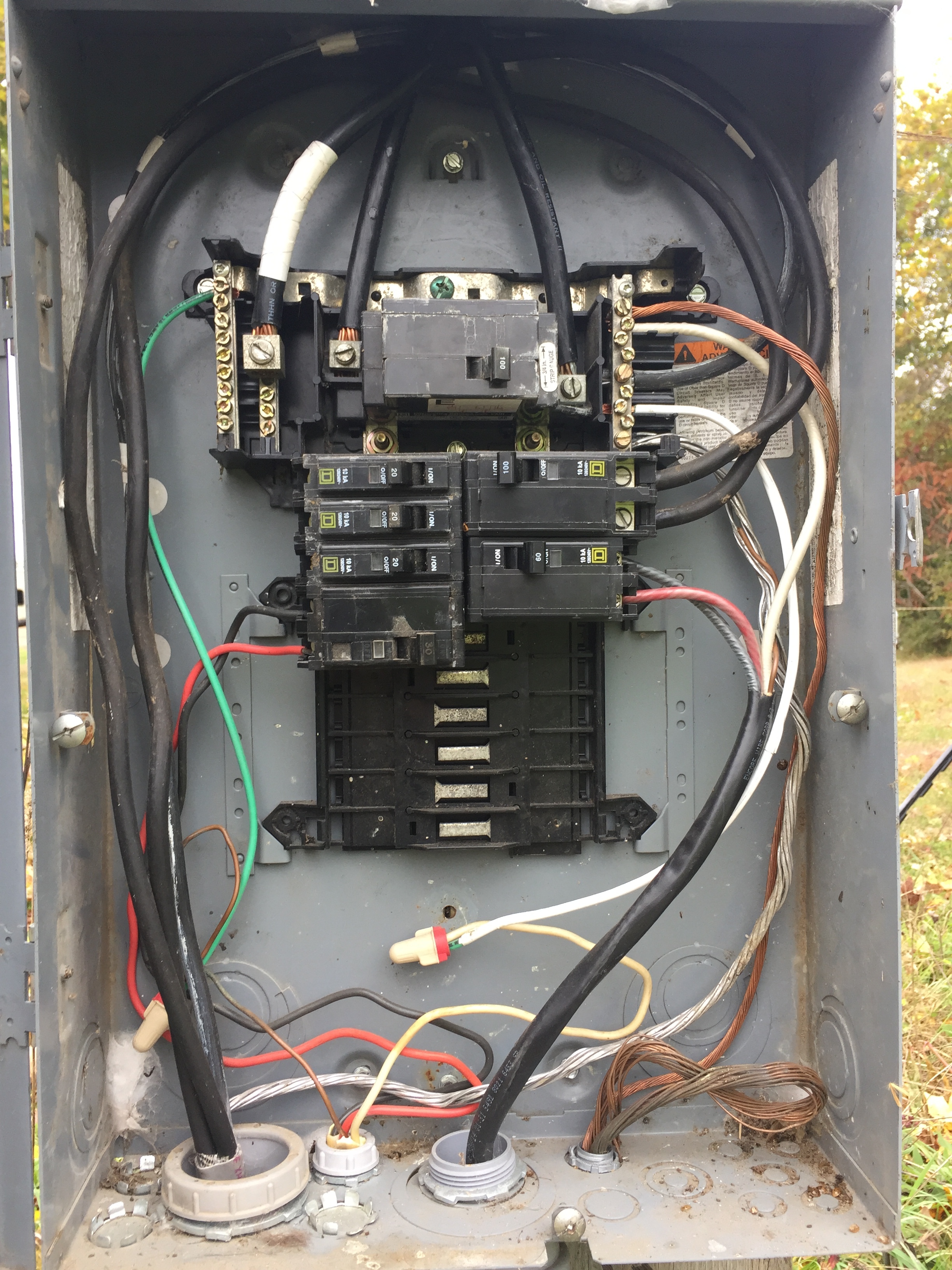
(I totally was wearing my arc flash gear when I pulled my my cover off live ha ha)
In the photo you can see the 2/0 cu feeds entering the panel from the utility meter. (They measured 13mm dia with the insulation on them)
The 30a breaker on the bottom left is the 240/120 I speak of for the well house. (The controls are all mechanical pressure switches)
The top right is the line feeding the house main breaker panel.
No CTs yet.
@Bill.Thomson Help!
I’m not familiar with your style of distribution panel. Is that incoming cable that’s bound with white tape a neutral or an earth (or is your earthing system TT?)
I’m sorry, I was assuming you’re used to midwest US wiring… Wiring code states a neutral wire should always be identified as white, and if the wire coating is the same as the hot wires (black) it needs to have white markings (i.e. tape or paint)
Dedicated ground wires are stripped of any insulation.
The two lines coming into the top of the panel, that tie into the two lugs next to the 100A circuit breaker are the two hot wires (L1 & L2 = 240V)
The white tape wrapped next to the left main hot is the neutral (allowing for L1 OR L2 to N = 120V)
The ground and the neutral are bonded in my part of the US (as visible in by the bus bar at the very top anchored with the green screw)
The bottom right 60A is unused currently; and is a way for me to allow me to connect my generator to this panel to run my well in the event of a power failure; and why it is turned off - eventually this is where my solar system will be connected.
Further explanation, the well’s power (red and black connected to the bottom left) uses the 240 volts for the motor, and the red wire to common (white) for the 1200W heater.
The feeder (incomer) with the white tape is a neutral. The grounds are the green and the bare wires.
We use a TN-C-S system.
Don,
With 2/0 Copper, you might find it a challenge getting a YHDC CT to close completely. When closed, split-core CT core faces must touch each other. Even a very small gap will interfere with operation. i.e. cause incorrect readings.
(I’m jealous. I wish I had that much room in my load center!)
That’s the way it should be done anywhere in the US. (If wiring is done to code)
Robert,
The second leg of a 240V branch circuit (as opposed to a feeder) is supposed to use a conductor with red insulation. However, depending on who installed the wiring, and when, that may not be the case.
This is my outdoor panel; you Don’t want to see what they put in the house. (Though I’ll post a completion pic when I get that far)
I am ashamed to say though, the two lines feeding my house, look to be cough 4ga cough al wire. At least half the wire in this panel is done well.
 (One of my main reasons for choosing this solution)