SCT013 value consistently too low

That looks very good!!! Live data also reasonable (PV + small consumers, then with toaster), all fine. Let’s see tonight.
Also I improved my spreadsheet, attached:
PhaseCal-Generic.ods (544.3 KB)

The yellow data must be entered/configured, maybe some comments might be helpful …

Updated EmonLib code (the interesting part):

void EnergyMonitor::calcVI(unsigned int crossings, unsigned int timeout)
{
  #if defined emonTxV3
  int SupplyVoltage=3300;
  #else
  int SupplyVoltage = readVcc();
  #endif

  unsigned int crossCount = 0;                             //Used to measure number of times threshold is crossed.
  unsigned int numberOfSamples = 0;                        //This is now incremented

  //-------------------------------------------------------------------------------------------------------------------------
  // 1) Waits for the waveform to be close to 'zero' (mid-scale adc) part in sin curve.
  //-------------------------------------------------------------------------------------------------------------------------
  unsigned long start = millis();    //millis()-start makes sure it doesnt get stuck in the loop if there is an error.

  while(1)                                   //the while loop...
  {
    startV = analogRead(inPinV);                    //using the voltage waveform
    if ((startV < (ADC_COUNTS*0.55)) && (startV > (ADC_COUNTS*0.45))) break;  //check its within range
    if ((millis()-start)>timeout) break;
  }

#define NUM_SAMPLES 1000
#define LOOP_DELAY  100

#ifdef NUM_SAMPLES
  printf("TGE PIN I: %d, U: %d\n", inPinI, inPinV);
  printf("TGE ADC range: %d\n", ADC_COUNTS);
  printf("TGE Supply: %dmV, vCal: %.2f, phaseCal: %.2f\n", SupplyVoltage, VCAL, PHASECAL);
  unsigned long tgeNow = millis();
  printf("TGE start %ld Timeout: %ld, now: %ld -> %ldms\n", start, timeout, tgeNow, (tgeNow - start));
  printf("TGE startV %ld\n", startV);
  printf("TGE start Offsets: I: %.2f U: %.2f\n", offsetI, offsetV);
  struct timeval t1;
  // struct timeval t2;
  struct timeval tLast;

  uint samplesI[NUM_SAMPLES];
  uint samplesV[NUM_SAMPLES];
  unsigned long samplesT[NUM_SAMPLES];

  gettimeofday(&t1, NULL); // TGE
#endif // NUM_SAMPLES

uint phaseCalInt = (uint) PHASECAL; // as int type
double phaseShiftedI;
double pcSamplesI[100]; // PHASECAL cannot be more than 100

  //-------------------------------------------------------------------------------------------------------------------------
  // 2) Main measurement loop
  //-------------------------------------------------------------------------------------------------------------------------
  start = millis();

  while ((crossCount < crossings) && ((millis()-start)<timeout))
  {
    numberOfSamples++;                       //Count number of times looped.
    lastFilteredV = filteredV;               //Used for delay/phase compensation

    //-----------------------------------------------------------------------------
    // A) Read in raw voltage and current samples
    //-----------------------------------------------------------------------------
#ifdef NUM_SAMPLES
    tLast = t1;
    gettimeofday(&t1, NULL); // TGE
#endif // NUM_SAMPLES
    sampleV = analogRead(inPinV);                 //Read in raw voltage signal
#ifdef NUM_SAMPLES
// gettimeofday(&t2, NULL); // TGE
#endif // NUM_SAMPLES
    sampleI = analogRead(inPinI);                 //Read in raw current signal

    //-----------------------------------------------------------------------------
    // B) Apply digital low pass filters to extract the 2.5 V or 1.65 V dc offset,
    //     then subtract this - signal is now centred on 0 counts.
    //-----------------------------------------------------------------------------
    offsetV = offsetV + ((sampleV-offsetV)/1024);
    filteredV = sampleV - offsetV;
    offsetI = offsetI + ((sampleI-offsetI)/1024);
    filteredI = sampleI - offsetI;

    //-----------------------------------------------------------------------------
    // C) Root-mean-square method voltage
    //-----------------------------------------------------------------------------
    sqV= filteredV * filteredV;                 //1) square voltage values
    sumV += sqV;                                //2) sum

    //-----------------------------------------------------------------------------
    // D) Root-mean-square method current
    //-----------------------------------------------------------------------------
    sqI = filteredI * filteredI;                //1) square current values
    sumI += sqI;                                //2) sum

    //-----------------------------------------------------------------------------
    // E) Phase calibration
    //-----------------------------------------------------------------------------
    if(phaseCalInt > 2)
    {
      // Store 100 samples in a circular buffer
      pcSamplesI[numberOfSamples % (sizeof(pcSamplesI) / sizeof(pcSamplesI[0]))] = filteredI;

      // High sampling rates and/or large phase errors - use I value <PHASECAL> samples in the past
      // If I is ahead of V
      phaseShiftedV = filteredV;

      // Which sample do we want?
      uint refSample = numberOfSamples - phaseCalInt;

      // Chose val depending on whether we already have that val, if so determine right index in circular buffer
      phaseShiftedI = (numberOfSamples > phaseCalInt ? pcSamplesI[refSample % (sizeof(pcSamplesI) / sizeof(pcSamplesI[0]))] : 0);
    }
    else
    {
      // "Classic" phase calibration, tune V value with previous sample
      phaseShiftedV = lastFilteredV + PHASECAL * (filteredV - lastFilteredV);
      phaseShiftedI = filteredI;
    }

    //-----------------------------------------------------------------------------
    // F) Instantaneous power calc
    //-----------------------------------------------------------------------------
    instP = phaseShiftedV * phaseShiftedI;      //Instantaneous Power
    sumP +=instP;                               //Sum

    //-----------------------------------------------------------------------------
    // G) Find the number of times the voltage has crossed the initial voltage
    //    - every 2 crosses we will have sampled 1 wavelength
    //    - so this method allows us to sample an integer number of half wavelengths which increases accuracy
    //-----------------------------------------------------------------------------
    lastVCross = checkVCross;
    if (sampleV > startV) checkVCross = true;
                     else checkVCross = false;
    if (numberOfSamples==1) lastVCross = checkVCross;

    if (lastVCross != checkVCross) crossCount++;

#ifdef LOOP_DELAY
    sleep_us(LOOP_DELAY);
#endif // LOOP_DELAY

#ifdef NUM_SAMPLES
    if(numberOfSamples <= NUM_SAMPLES)
    {
      samplesI[numberOfSamples - 1] = sampleI;
      samplesV[numberOfSamples - 1] = sampleV;
      samplesT[numberOfSamples - 1] = tLast.tv_usec;
    }
#endif // NUM_SAMPLES
  }

#ifdef NUM_SAMPLES
  unsigned long tgeNow2 = millis();
#endif // NUM_SAMPLES

  //-------------------------------------------------------------------------------------------------------------------------
  // 3) Post loop calculations
  //-------------------------------------------------------------------------------------------------------------------------
  //Calculation of the root of the mean of the voltage and current squared (rms)
  //Calibration coefficients applied.

  double V_RATIO = VCAL *((SupplyVoltage/1000.0) / (ADC_COUNTS));
  Vrms = V_RATIO * sqrt(sumV / numberOfSamples);

  double I_RATIO = ICAL *((SupplyVoltage/1000.0) / (ADC_COUNTS));
  Irms = I_RATIO * sqrt(sumI / numberOfSamples);

#ifdef NUM_SAMPLES
  printf("TGE end meas loop: %ldms NumSamples: %d (%d)\n", (tgeNow2 - tgeNow), numberOfSamples, phaseCalInt);
  printf("t;ADC V;ADC I\n");
  for(int i = 0; (i < NUM_SAMPLES && i < numberOfSamples); i++)
  {
    printf("%ld;%d;%d\n", samplesT[i], samplesV[i], samplesI[i]);
  }
  printf("TGE Vrms: %.2fV\n", Vrms);
  printf("TGE Irms: %.2fA\n", Irms);
#endif // NUM_SAMPLES

  //Calculation power values
  realPower = V_RATIO * I_RATIO * sumP / (phaseCalInt > 2 ? (numberOfSamples - phaseCalInt) : numberOfSamples);
  apparentPower = Vrms * Irms;
  powerFactor=realPower / apparentPower;

  //Reset accumulators
  sumV = 0;
  sumI = 0;
  sumP = 0;
//--------------------------------------------------------------------------------------
}

I set phaseCal=26 (as determined above).
All to be reviewed and cleaned up, but at least to me that looks promising.

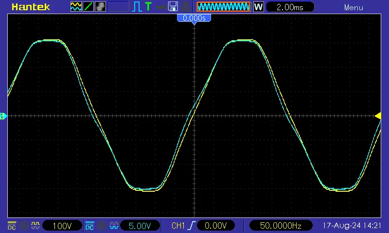
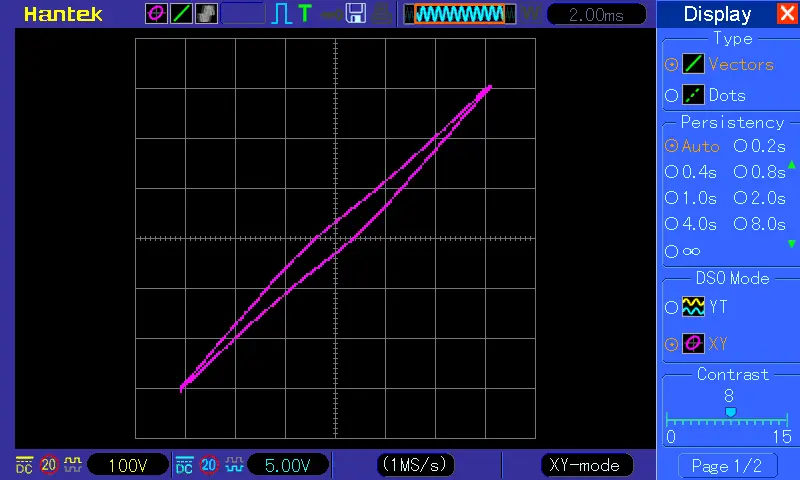
The question, where that phase error came from is still open, I will try to find out (VT + oscilloscope). The VT seems to contain a thermal fuse at least:
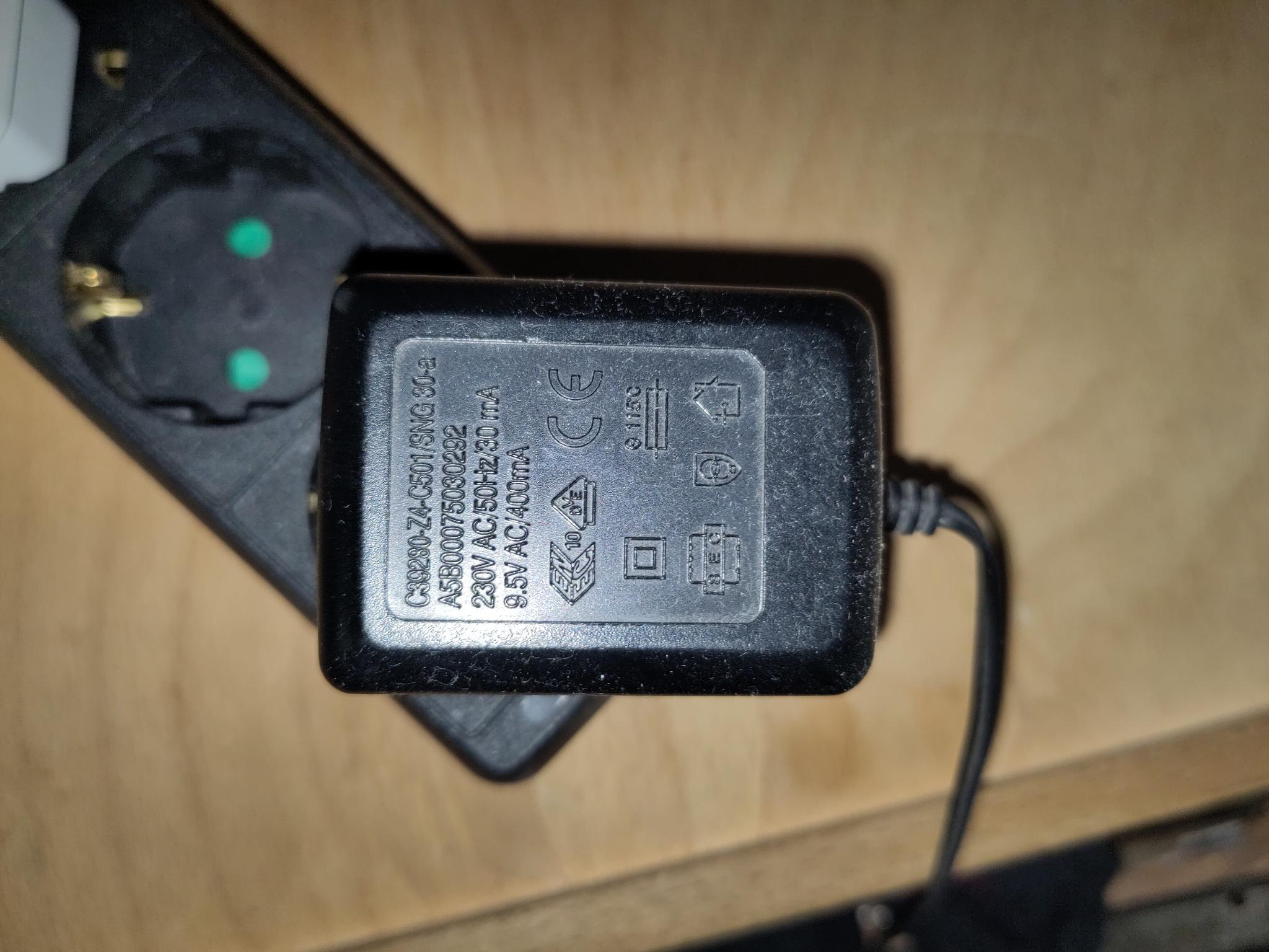

(Symbol under “CE”)

I expected this would be the case. I would hope there is nothing else in there - but if there is, why? We shall probably never know. I find it really hard to believe a simple transformer can generate a phase shift of 30 - 60°. This is a UK “Ideal” a.c. adapter as sold by the OEM shop. Yellow is the mains 240 V, blue is the 9 V output.


and in X-Y mode:

The adapter was “Ideal No.2” in my report.

I agree. I was looking for a reason why you were seeing a large phase shift. If your load was the toaster plus a big reactive load, then the phase shift was real and so was your power reading, but if not, it was your measurement that was wrong.

Correct.

:smiley:
I can understand that.
This is exactly what I needed to do in emonLibDB to cater for the much faster Microchip AVR128DB48. A very short explanation: Every sample, voltage and current, is recorded in a circular array as it comes in, and pairs of samples (one voltage, one current) are selected from the array to be multiplied together (= instantaneous power) and then averaged to give the average real power. Slightly more complicated version: it’s not a single voltage sample, it is two consecutive ones and the interpolation for phasecal is done using what I call “partial powers” when the calculations and averages are done at the end of the reporting period. Oh, and it’s all done with interrupts, so some code is setting up the ADC for what it must do next, and then it is handling the result of what the ADC has just done :open_mouth: :exploding_head:. This takes time to understand. The emonLibDB library is available on Github if you really want to see how it works.

This might be good enough, or you might find that calculating the power factor (= real power / (Vrms × Irms) ) and adjusting the “26” to give a power factor closest to 1.0 is more accurate.

I’ll look through your code and the spreadsheet later (hopefully today or tomorrow).

A few observations on your emonLib code:

You can simplify some of the buffer array indexing by making the array 128 elements long instead of 100, and then using a bitwise ‘AND’ to mask all but the lower 7 bits (so when it overflows from 127 (01111111 B) the high bit is lost). From emonLibDB:
++sampleCount &= (RAWSAMPLESSIZE-1);
so your line 100
pcSamplesI[numberOfSamples % (sizeof(pcSamplesI) / sizeof(pcSamplesI[0]))] = filteredI;
might become something like this:
pcSamplesI[numberOfSamples & (BUFFER_SIZE-1)] = filteredI;
This only works when the buffer size is a power of 2. Provided your buffer is bigger than the delay in samples, it will work (so 32 = 25 would be OK).

The filtered V & I should settle to a constant value with no ripple, so I think you need to change the time constant (by reducing the proportion fed into the offset in lines 77 & 79), alternatively you can throw that filter away and use the maths that says the rms of a signal plus an offset is √(signal² + offset²) - so you accumulate (signal+offset)² and offset – the average offset being of course the average of the signal itself) and rearrange the equation to give signal² = (signal+offset)² - offset². And you do this last part once only “post loop”, when you report the values. This means you do only simple maths (+ ×) for each sample, no division (which is slower).

There must be a better way of doing line 110. I have not thought this through, because it’s important to keep a constant sample rate when you’re calculating rms values, but would it be simpler to zero the accumulators on the 26th (=phasecal) sample and then subtract this (26) from the number of samples to keep the averages correct? It doesn’t matter if you calculate rubbish values for the instantaneous power if you are going to discard them.

There is a way to get to your phasecal value without the spreadsheet: shift the current until the power factor falls to zero. This means your resistive load now appears to be wholly reactive and the true phase error must be 90°, so subtract 90° of samples from the number for phasecal to get the value to use. You could alternatively use p.f. = 0.5 and subtract 60° of samples, but zero is an easy number to use, and p.f. is changing fastest at 90°.

Many thx again first of all! How do we proceed with this in general? If it were just me - I’m happy now: It’s been running for a couple of days now, all data looks fine.
However, I’d hope that this might also help others, so would we integrate this into the official code? In addition I have a small “wrapper” for making it run on the RPi Pico (some of the Arduino lib calls don’t exist there).

And, a few other thoughts:

  • Do we need to worry about V being ahead of I?
  • I ordered a second SCT013 for the brown wire but would like to re-use the VT. Now, being on different phases, it should be possible with the same trick as above to adjust the phase shift between V(L1) and I(L2)? Btw: for some reason there is no L3 in my appt. Nevertheless, I imagine a new calcVI3(pinV, pinI1, pinI2, pinI3) or so …

Regarding your other proposals - I’m afraid I have to digest that again for a bit :slight_smile:
Btw: The spreadsheet helped me a lot to understand by actually seeing the curves from real data.

I think the first step is to make sure everything works correctly, and the readings are accurate. Next will be to make certain that all your notes are complete and accurate, so that when you come back to this in the future, you will know what you did and probably more importantly, why you did it.

I don’t want to denigrate your work, but you started with the obsolete emonLib, which in the original design recorded the power for 200 or 300 ms every 10 s. We introduced continuous monitoring, where the power is measured truly continuously, about 6 years ago so my feeling is, this method is likely to be favoured because it is capable of measuring rapidly varying loads more accurately, especially in the short term.

Provided that you can record a unity power factor when you have a purely resistive load, no. You can swap the order in which voltage and current are read if you wish, it makes sense to arrange it so that you need the minimum shift in time of whichever quantity you choose to shift.

Really? Are the two voltages always close enough in amplitude so as not to introduce an error? If your answer is yes, then delay the second current by 120° and treat the two currents identically. You will probably want to read V1, I1, I2 in sequence so that you reduce the overall sample rate for each phase (which I think you can afford to do), but the results apply to the same measuring period. If your answer was no, then read V1, I1, V2, I2 or V1, V2, I1, I2 whichever makes the most sense regarding the delay you need to compensate for the phase errors.

I seem to remember I’d read many years ago this was normal somewhere in the world – but I’d forgotten it completely. My guess is, the reason is cost - they thought at the time you would not need all three phases so why pay the extra cost for a supply cable, larger distribution board and more circuit breakers etc? In the UK, a single phase (at 60, 80 or 100 A) has been standard for many years, however I believe the intention is that newly built housing will be cabled for three phases (i.e. the main cables buried under the roads, already 3-phase, will continue into the house as three phase), anticipating a greater demand due to the widespread use of heat pumps and electric vehicles.

I just created a git fork (GitHub - tge12/EmonLib: Electricity monitoring library - install in Arduino IDE's libraries folder then restart the IDE) and uploaded all my stuff - so at least it is not lost, whatever may happen with it.
Beautified everything a bit, adopted your proposed optimizations, right now it’s running again, for testing a while. So far, looks good.
I also inserted an “if(phaseCal < 0) block” (idea: V ahead of I) which basically does the same as in the original version, but tbh after reading your latest post again, probably we can kick that out again …

EmonLibCM … well, I looked at it, but that would mean to start over again, it’s a lot more complex and I’d even need some new hardware (radio stuff), so admittedly that would not be my first choice. Right now I even call calcVI only every 10s (to reduce DB data on server) and the results actually look quite good to me. Calling calcVI as often as possibly (and pre-processing outside of EmonLib) would an theoretical option to improve data quality, also I’ve seen other applications with DMA-based data reading, which would then result in something close to CM - but all of that seems not really needed (for me) as of now.

Regarding the same VT for L1 and L2 - actually I was assuming that V is “the same” on L1 and L2, but yes, why should it be. Unfortunately, cabling another VT to an L2 wall socket will cause me more headaches - if ever possible, I’d skip that (maybe on the expense of data quality). I will just give it a try with one VT, let’s see :slight_smile:

Finally, yes, also the fact, that obviously nobody else has any problems like me (??) sounds as if nobody uses the “classic” EmonLib anymore … so let’s close the topic. If somebody really cares, everything is here and/or in my git fork.
THANKS A LOT again for all your help + the outstanding web site and everything!

1 Like

I’m really pleased to read that you are happy with your project. It is not that nobody uses emonLib any more, it is a valuable resource for learning how to measure and calculate electrical power and energy, and people do use it and ask questions about it from time to time. In fact, in the long term, there is very little difference between emonLib and emonLibCM if both have been carefully calibrated. The big difference is in the short term and especially if you have appliances that switch on and off very frequently, And this is a big reason why we (the OEM Shop) no longer send out products with emonLib as the default software - with one important exception: when batteries are the only source of power. It was only fair to you that I mentioned emonLibCM (and emonLibDB works very much the same way - but with important differences because of the different processor with better capabilities), so if at some point you want to improve your monitor - or even just expand your knowledge, then you have a starting point.