Hi everyone, I am using ESP 12 in combination with ADS1115 and SCT013 transformers to measure the power of AC appliances, but there seems to be some problems with my circuit diagram and code.
Could anyone please give me some advice? (2 sensors connecting to PC)
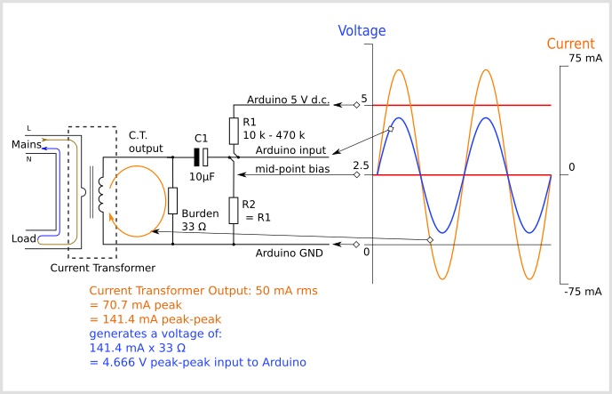
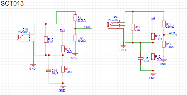
Circuit:
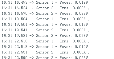
Result:
Code:
#include <Wire.h>
#include <Adafruit_ADS1X15.h>

Adafruit_ADS1115 ads;

const float ADC_BITS = 32768.0;
const float GAIN_VOLTAGE = 2.048;
const float MULTIPLIER = GAIN_VOLTAGE / ADC_BITS;
const float SENSOR_SENSITIVITY = 1.0 / 30.0;
const float RESISTOR = 22.0;


const float FACTOR = MULTIPLIER / (SENSOR_SENSITIVITY * RESISTOR);

void setup() {
  Serial.begin(9600);
  ads.setGain(GAIN_TWO);
  ads.begin();
}

void printMeasure(String prefix, float value, String postfix) {
  Serial.print(prefix);
  Serial.print(value, 3);
  Serial.println(postfix);
}

void loop() {
  float currentRMS1 = getCurrentRMS(0);
  float currentRMS2 = getCurrentRMS(1);
  float power1 = 110.0 * currentRMS1;
  float power2 = 110.0 * currentRMS2;

  printMeasure("Sensor 1 - Irms: ", currentRMS1, "A ,");
  printMeasure("Sensor 1 - Power: ", power1, "W");
  printMeasure("Sensor 2 - Irms: ", currentRMS2, "A ,");
  printMeasure("Sensor 2 - Power: ", power2, "W");
  delay(1000);
}

float getCurrentRMS(int channel) {
  float sum = 0;
  int counter = 0;
  long startTime = millis();

  while (millis() - startTime < 1000) {
    int16_t adcReading;
    if (channel == 0) {
      adcReading = ads.readADC_SingleEnded(0);
    } else if (channel == 1) {
      adcReading = ads.readADC_SingleEnded(1);
    }
    float voltage = adcReading * MULTIPLIER;
    float current = voltage / RESISTOR;

    sum += sq(current);
    counter++;
    delay(1);
    yield();
  }

  float rms = sqrt(sum / counter);
  return rms;
}