Hello, good day! I’d like to ask inputs from you guys please. I have this ESP8266 + The Clamp sensor I used the 5v supply from the ESP and I use 33ohms resistor. For testing purposes I tried measuring my Rice Cooker using Fluke clamp meter and it reads 3.01.
Using my SCT013-100 my reading shows this:
Watts Current
639.4 2.78
722.2 3.14
653.2 2.85
and so on…
It has a big amount of discrepancy, I already did the calibrations, its just that it reads inconsisently. Is that normal?
Hi Sir, i’m using arduino IDE. Same circuit shown into the openenergy current sensor only. Im using 5v and 33ohms, alreay adjusted the calibration. If im measuring less than 1A the measurement error is high, but if its above 1A minimal error. Thanks
Noise. We think that electrical noise, maybe coming from the digital circuits inside the Arduino, maybe from the power supply, maybe even on your electricity supply, gets into the analogue to digital converter somehow, and spoils the reading. It might also be noise on the circuit you are measuring that is being picked up by the c.t. itself.
Any c.t. is inherently inaccurate at very low currents. Your SCT-013-000 (I think you gave a wrong part number) is quoted as ±3% between 10% and 120% of rated current, i.e. between 10 A & 120 A. Outside of that range, there is no guarantee of accuracy.
What will help with both these things is a multiturn primary winding for your c.t. Normally, you clip the c.t. onto a wire and it passes once through the aperture. If you pass it through many times, you divide the maximum current by the number of times the wire passes through, and you equally reduce the current at which you see the problem. Of course, you must adjust the calibration constant in exactly the same proportion.
Therefore, if you pass the wire through 10 times, you can only measure up to 10 A (10 × 10 = the 100 A maximum), but you should have minimal error above 100 mA instead of above 1 A.
The number of times you can pass the wire through is limited by the size of the aperture. You must not force the c.t. to close, because the ferrite core is extremely brittle and it will break if stressed. Do not use a thin wire and risk a fire, the wire must always be able to carry the maximum current that you will use, without getting hot.
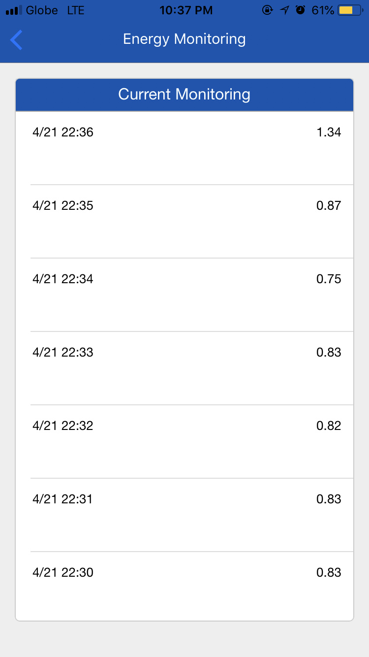
Hi sir, applogy. I didnt get that. What youre trying to say is that for me to have accurate reading I should use a lesser c.t like 30A maximum? Because i am only measuring a solar panel, when its hot, the measurement is 1A up so i got minimal current. But when its not so hot, the measurement is less than 1A it is inaccurate. Attached is a sample reading coming from the solar panel.
Read again what I wrote above about a multi-turn primary winding for your c.t. That is how you convert it.
If you cannot get enough turns through the c.t. to get the maximum down to 5 A or so, then the next thing is to change the burden resistor. But that will give you different errors, so a many-turn primary winding is the best to begin with.
You could, if you can find a suitable c.t. - one that has a high VA rating so that it can generate the 5 V peak - peak (~ 1.6 V rms) that your Arduino needs.
But winding several turns of wire for the primary winding costs you nothing.
I thought a free and simple solution using what Banjing already had was easier, however, it is up to him what he does. I’ve tried to explain what to do, there appears to be some sort of problem - possibly in translation - with that.
Given he’s measuring only about 1 Amp, one would think his wiring should be small enough to easily be able to make more than one pass through the CT. But, he may not have enough slack in his wiring to use the multi-turn method. I’ve run into that issue in my load center as well as with my PV system (although for not quite the same reason) which is why the thought occured to me.
I use an ESP8266 primarily for pulse counting on import and generation meters, but I also have a CT sensor to measure household consumption when generation > use. From this experience I can offer the following advice:
There is only one ADC on the ESP8266 so you can’t correct for power factor
The ADC is 10-bits (like standard Arduino)
Although a 3.3V device, the ADC has a temperature compensated Vref of ~1V (I’m using a bare ESP8266 module for minimum cost/footprint, I don’t know if there are other options when integrated into boards)
In order to bias the ADC to about 0.5V I used a 56k / 10k potential divider (just changing component values from those shown elsewhere on this site that divide Vcc by 2)
I started with a CT sensor marked ‘1V / 30A’. This had a surface mount resistor on it marked as 62 ohm (it can’t be measured in circuit as the CT winding is in parallel). I In order to reduce the CT output to (very approximately) ‘1V / 60A’ I placed a 68.3ohm metal film resistor in parallel (within my equipment, not in the probe where there isn’t much room)
I then measured the DC offset as seen by the ESP8266 with the CT probe input shorted out, and removed the offset. In terms of the ‘model code’ shown on this site (which I didn’t use as I’m doing pulse counting), this means removing the calculation for ‘offsetI’ and replacing it with the DC offset measured in practice.
I then connected the sensor and checked that I got low power readings when not clamped over a wire
I then calibrated the sensor (like the original poster) using a 3kW kettle.
I forgot another thing I did to get to ~2% accuracy.
I checked the ADC measurement speed using the Arduino ‘micros’ command. I’m not sure of the stability of the ESP8266 clock module, but I measured 103uS+/-3uS per measurement.
I set the ESP8266 to take 1941 measurements to return a reading. This is in order to average over 10 complete 50Hz mains cycles. If your mains is 60Hz and had the same ESP8266 module then I’d recommend 1618 measurements.
If these steps are done with some attention to detail, then a CT sensor can be used with an ESP8266.
When not exporting I can compare my CT reading of household use with the dual-meter pulse-counting measurement (import + generation). With relatively heavy loads (e.g. kettle on, power factor = 1) I observe the CT sensor within about 2% of the pulse measurements, but at low power consumption dominated by loads such as fridge-freezer and central heating pump the combination (I guess) of noise plus power factor means that the CT sensor typically reads 5 - 11% over, and the worst I’ve seen is 17% over (although as the pulse counting doesn’t give an instantaneous measurement, so there could have been a transient power use that exaggerated the difference in this case).
Thank you for those comments. What you’ve done is pretty much in line with my recommendation (from another old fogey, in the linked thread). It’s good to know that the 1 V reference and the supply are both sufficiently stable for you to be able to remove the offset as a hard-coded constant. Obviously, we can’t take that approach when component tolerances come into play on a production run (unless each one is individually calibrated).
Thanks for the positive feedback. I forgot another thing I did to get to ~2% accuracy.
I checked the ADC measurement speed using the Arduino ‘micros’ command. I’m not sure of the stability of the ESP8266 clock module, but I measured 103uS+/-3uS per measurement.
I set the ESP8266 to take 1941 measurements to return a reading. This is in order to average over 10 complete 50Hz mains cycles. If your mains is 60Hz and had the same ESP8266 module then I’d recommend 1618 measurements.
These clamps are a little fragile - they have a black ferrite core. I once had a cracked one that gave inconsistent readings. just a thought - worth a visual inspection.
The Vref is an internal reference, not accessible from the outside. So you don’t apply more than 1V to the analogue input (pin2). Best thing to make it clear is to try it with a simple sketch - apply 0V, 0.5V and 1V to analogue input and see what results you get.