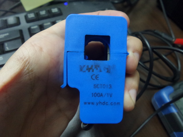
SCT-013-000 very confused!

I’m discovering all this, so please bear with me while I try to explain what I did!

First of all, I started with the assumption hat the schematics of using SCT-013-000 with Arduino ended up with a DC 0-3.3V voltage on my A0 pin because I thought it was the very purpose of C1 to flatten the voltage.

Wrong I was, I understand that now, and I have to use the emon library to measure the current and do a correct reading of the wave.

Now I get more consistent result, but it’s kind of jumping a lot still :

839.29 7.63
775.94 7.05
763.13 6.94
814.84 7.41
942.24 8.57
861.98 7.84
805.77 7.33
757.18 6.88

My burden is 43ohm, and I’m doing this on a Arduino Uno using the 3.3V, later on a ESP8266

It’s still unclear in my head even after reading the doc what the calibration value should be, I’m just using Amp and I know exactly the current power usage monitoring my meter.

I had to put this

emon1.current(A1, 450.1);             // Current: input pin, calibration.

Does it sounds right? Anything I’m missing that would lead to inconsistent values?

Thanks!

What sketch are you using, and how is your hardware configured?

Have you read the Resources > Building Blocks article that explains the calibration theory? Near the end, that gives the formula for calculating the calibration constant based on the burden resistor value and the current transformer ratio. Without even getting my calculator out, I think 450 is way too big, it should be nearer to 45. But until you tell us what those numbers are supposed to represent, we cannot really help you. Remember that the SCT-013-000 is only specified down to 10 A. If you are trying to measure a very small current (i.e. less than 1 A), then you are probably seeing electrical noise.

Thanks for your answers!

Sensor : CTYRZCH SCT-013-000, rated for 50mA out
Hardware : Arduino Uno
Burden : 43 Ω
Divider : 2x10kΩ

I’m measuring from the main cable out of the meter, so the current should be significant, between 3 and 30A I would say

Sketch after reading the doc another time and trying my best, also logging the int value from the analog input and putting the actual V reading from a wall plug at 124V.

I realize logging the raw A1 doesn’t make much sense as the irms is not calculated over a cycle

#include "EmonLib.h"                   // Include Emon Library
EnergyMonitor emon1;                   // Create an instance

void setup()
{  
    Serial.begin(9600);
    emon1.current(A1, 46.51);             // Current: input pin, calibration.
}

void loop()
{
    int i=0;
    double Irms = emon1.calcIrms(1480);  // Calculate Irms only
    Serial.print(analogRead(A1));
    Serial.print(" ");
    Serial.println(Irms*124.0);         // Apparent power
}

This morning the house is drawing power again, here is the values I get with the calibration calculated from the following formula :

current constant = (100 ÷ 0.050) ÷ 43 = 46.51 // Not sure what 0.05 is?
247 1595.19
263 1598.20
329 1605.72
387 1597.13
414 1599.26
365 1602.25
311 1603.03
253 1596.80
253 1595.63

The true W is ~2200

If I unplug the sensor, that’s the “noise” I’m getting :

330 10.44
331 10.70
330 9.96
330 11.15
330 10.16
330 10.98
330 10.68

Thanks again for the help!

Sensor : CTYRZCH SCT-013-000, rated for 50mA out
____________________________________^ The CT secondary current at the rated primary current!

You could forget the instantaneous voltage on A1, with current flowing, it means very little. But it is a useful check for your assembly: with no current flowing it should be a steady value close to 511. So I think there is a fault somewhere in your construction, 330 is not right.
Approx 10 W of noise is about what most people see with an Arduino and breadboard.

Ah, makes sense indeed.

Actually I just found out that what I think is out of the meter, is actually not. A hair dryer running makes the disk spin faster roughly 1500W, but it is not registered by the Arduino (but the air conditioning for example is registered both on the disk and the arduino.

Something is really funky in this installation, that’s actually why I’m working on this.

I will try to understand why I get steady 330 instead of 511 though. I’m running the 3.3V of the Uno, does that makes a difference?

it should not. The bias voltage should come from the general supply to the Arduino - the same that is used as the reference voltage to the ADC. If that is 5 V, and you’re using 3.3 V for the bias, then that explains the 330.
If you temporarily connect A1 to the 3.3 V, what do you read? It should be 1023 or thereabouts, if it is 676 or so, that’s what you’ve done.
In that case you need unequal resistors, or bias off the 5 V supply, to make the bias voltage 2.5 V and the no-input count 511.

And have you read the “Use in North America” page? That might be useful to you.

Ha! You mean the library reads the main power supply for the Arduino? Then yes, That’s 5V, but I’m using the 3.3V out of the UNO for the circuit because eventually I will be using a ESP8266 that is full 3.3V, I thought it would be a good idea :slight_smile: Did I get that right?

Now, I’m doing some measure comparison : orange comes from a laser counting the meter revolutions, green is the SCR-013-000 circuit.

When I turned the A/C on, I get a +1283W on orange, and +828W on the green. Is that a calibration issue? Am I actually measuring the same thing at the meter and at the clamp, or in other words, are we talking about the same “amps”.

Should I calibrate and try to get the same values, is that even possible or a waste of time?

Could that actually caused by the voltage difference between Arduino DC in and measure circuit?

I realize that’s a lot of question and I thank you guys for the patience with an electricity noob!

And so does the analogue input. And it is the reference voltage for the ADC. So everything you read on the analogue inputs is related to 1023 = 5 V.

Not really.
You need to check the design of the input circuitry. It could be that the input is clipping (because of the lower voltage swing available because the input is not biased at the mid-point).

If you’re designing for a 5 V supply (Arduino), you calculate the burden to give 1.6 V rms at your maximum current. If you’re designing for a 3.3 V supply, you want 1.1 V rms at max current. Those numbers take component tolerances into account and leave a bit of headroom.

I think you need to show all your design calculations, because it looks as if you are in a complete mess.

Also, bear in mind that your meter almost certainly reads real power, your Arduino will only be able to guess apparent power based on your estimate of the system voltage and an assumption that the power factor of your load is 1.0 (it won’t be with induction motors etc running).

Ok I’m waiting for the Wemos to arrive, I’ll go back to the drawing board then. I did the math considering a 3.3V circuit, so indeed my understanding is that A1 is getting less than expected capped at 1.1V + (3.3/2) = 2.75, that would explain that, applying a 1.51 factor to the numbers on my graph, I’m almost aligned as you can see :

.

As you said, the voltage will probably vary and what is 124V today might be different tomorrow.

It doesn’t seem like I’m capping as I couldn’t get any plateau, up or down, if I’m capping indeed, that would be at values I’m not reaching (even unplugged, I get some noise more than zero).

For the record, that was my calculation :

Ideal burden resistance
= (AREF/2) / Secondary peak-current
= 1.5 V / 0.0500 A
= 45.04 Ω

Now I can see 1.5 should actually be 1.65, so :

Ideal burden resistance
= (AREF/2) / Secondary peak-current
= 1.65 V / 0.0500 A
= 33 Ω

The final montage will be based on a Wemos D1 mini pro and a ADS1115 A/D converter that is more analog and higher resolution, I’ll have to check how the library deals with that then :smiley:

1 Like

That won’t happen. I said ‘clipping’, and it will happen on the negative half of what is supposed to be a sine wave. As it starts to clip, the negative half will gain a flat bottom, but the positive half will keep going. The rms value will no longer change linearly compared to before clipping started, but it will continue to increase in a complicated way. If you want to experiment, make a spreadsheet with one cycle of a sine wave made up of about 90 points, put a limit on the negative going values, and calculate the rms value and watch how that changes as you change the amplitude.

When you come to calculate the current calibration, you’ve got to remember that the voltage is swinging 1.65 V peak, yet because the bias is set to 1.65 V, the positive peak can only reach 3.3 V, or 676 counts. Therefore you will be reading low by 676 / 1023, which is pretty much what’s happening. There’s a 3% tolerance on the CT, and 1% probably on your burden, plus whatever on the Arduino’s supply rail, so expect your calculated calibration to be out by a few percent.

If you use a 3.3 V ADC, then it’s all going to change back to what you expected when you swap over.

Makes sense, Thank you so much! I’ll sample the analog input on the final circuit to make sure it stays in the A/D converter range!

Good day ladies and gentlemen,

I am a newbie in this group and also new with Arduino. Since 2 weeks ago, I have spent my time to build an electricity data logger for my study in college.

At this moment, I have no 240V AC to 9V AC adapter, so I decided only to use the SCT-013-000 sensor to get the current value based on the diagram in the link below:
CT sensors - Interfacing with an Arduino
While reading the content in this link, I noticed the following phrase:

If the CT sensor is a “current output” type such as the YHDC SCT-013-000, the current signal needs to be converted to a voltage signal with a burden resistor. If it is a voltage output CT you can skip this step and leave out the burden resistor, as the burden resistor is built into the CT.

The SCT-013-000 that I bought is printed (on the sensor itself) with information saying that the sensor produces output = 1V when the input is 100A. Based on my understanding, this means that the SCT-013-000 that I have is voltage output CT, NOT current output CT. Therefore, I conclude that I don’t have to use a burden resistor for my voltage output CT, as mentioned in the previous link.

I tried to double-check about this on the manufacturer’s website on the following link:
100A Split core current transformer SCT-013
There is the data sheet for SCT-013-000 in this link. Inside the datasheet, I found the schematic diagram for both current output type and voltage output type. Based on my understanding of the schematic diagram, the current output type is equipped with TVS diodes while the voltage type is equipped with TVS resistor, am I right? Therefore, I can omit the burden resistor for my situation because TVS resistor in my SCT-013-000 acts as burden resistor, right?

If my assumption about I don’t have to use burden resistor is correct, then the estimated value for the TVS resistor is calculated below:

There are 2000 output coils in SCT-013-000. If the input current, Ii is 100A, therefore Ii x Ni = Io x No, hence output current, Io = Ii x Ni/No = 100A x 1/2000 = 0.05A
If the input current 100A produces produces 0.05A and 1V at the output, that means the TVS resistor, Rtvs = Vo/Io = 1V/0.05A = 20Ω

I tried to use multimeter to read the value of resistance between the output terminals of my SCT-013-000 and obtained the value 16.6Ω. However, I think this measuring method is not accurate because the TVS resistor is connected in parallel with the 2000 output coils of my SCT-013-000. If the multimeter supply DC current/voltage to measure the value of resistor, the 2000 output coils will behave like an inductor supplied with DC current/voltage, which is a short circuit. Dismantling the SCT-013-000 just to disconnect the TVS resistor from the 2000 coils will damage the sensor. Therefore, at this moment I decided to stick with the TVS resistor = 20Ω, which is estimated and explained in the previous paragraph.

I use the code below for my Arduino UNO kit, which is downloaded from Open Energy Monitor website:

// EmonLibrary examples openenergymonitor.org, Licence GNU GPL V3

#include “EmonLib.h” // Include Emon Library
EnergyMonitor emon1; // Create an instance

void setup()
{
Serial.begin(9600);

emon1.current(1, 111.1); // Current: input pin, calibration.
}

void loop()
{
double Irms = emon1.calcIrms(1480); // Calculate Irms only

Serial.print(Irms*230.0); // Apparent power
Serial.print(" ");
Serial.println(Irms); // Irms
}

In one of the replies above, I noticed that Mr. Robert.Wall said that the value of the calibration constant should be near to the burden resistor value. Does this means that I should also revise my calibration value in the script above from 111.1 to 20 for my case?

Long story short, I would like to double check the following 2 things:

  1. I don’t have to use burden resistor because the SCT-013-000 that I have is voltage output type that comes together with TVS resistor.
  2. I have to revise my calibration constant in the code above from 111.1 to 20 if it is estimated that the value of TVS resistor for my SCT-013-000 is 20Ω
    Thank you very much and have a nice day.

Below is the photo of my SCT-013-000. The information saying that the sensor produces output = 1V when the input is 100A is printed on the sensor.

I just read one of the posting by Mr Robert.Wall about reading the Resources > Building Blocks article that explains the calibration theory. Below is the link:
Calibration Procedure

However, I found another additional information on the following link:
Installation and Calibration
This link teaches us to calculate current constant for both current output CT and voltage output CT. The formula is shown below:

current constant (for current output CT) = (maximum input current ÷ maximum output current) ÷ burden resistor value
i.e for SCT-013-000 current output type with maximum input current = 100A, maximum output current = 0.05A, and 18Ω:
current constant = (100A ÷ 0.05A) ÷ 18Ω = 111.11

current constant (for voltage output CT) = (maximum input current ÷ maximum output voltage)
i.e for SCT-013-000 voltage output type with maximum input current = 100A and maximum output voltage = 1V
current constant = (100A ÷ 1V) = 100

Based on the formula above, I don’t have to worry about the value of TVS resistor and don’t have to use burden resistor if I use the voltage output SCT type. All my questions in the previous 2 postings are answered. Thank you very much and sorry for disturbing. Have a nice day.

See About split core CTs SCT-013 family - #5 by foxfaisal

Throughout the above, you write “TVS resistor”. The component is not a resistor, its full name is Transient Voltage Suppression Diode. It is a 2-terminal semiconductor device with a highly non-linear V-I characteristic. Because of that, you will not read a sensible value of resistance. I suggest you look up the data sheet for one to see exactly what it does. It is connected across the secondary winding of a current transformer to clamp the voltage to a safe level should the burden become disconnected. It is most important that it does not shunt current away from the burden, and therefore it must conduct negligible current at the normal operating voltage across the burden resistor.

Dear Mr Robert.Wall,

Thank you for your feedback. I have explained how did I came up with the term ‘TVS Resistor’, which is available in the following links:

  1. The first explanation
  2. The second explanation

Thank you very much.

I’m implementing a second CT on the same Arduino device. What I did is just create another circuit, on the same 5V out, It seems my readings on the two CTs are different, is what I’m trying to do valid or should I make adjustments?

Basically, I have two dividers, two capacitors and two burden resistance and I split +5V to go on both circuits, one CT going to A0, the other on A1

What you’ve done sounds correct - have you compared it with the emonTx circuit diagram?

You should expect a small difference between the two. The tolerance on the CT is ±3% over the range 10% - 120% of rated current, to that add the tolerance of the burden resistor, and then it’s possible that the two sets are at opposite ends of the tolerance band. So you could have 8% difference between the two with 1% resistors. If your current is below 10 A, then the accuracy of the CT is not specified, and although my measurements indicate that generally it is well-behaved, there’s no guarantee what it will read.

1 Like

So, with a meter I get these values :

C1 : 1.9 x 124 = 235W
C2 : 0.8 x 124 = 99W

The Uno actually gives me :

C1 337.49
C2 181.21

Quite a stretch isn’t it?

My Burden calculation : (5 / 2) / 0.05 = 50 Ω, I used 47Ω

The calibration I used is (100 / 0.05) / 47 = 42.55

On the second topic, here is the resultst I get when swapping the two CTs, does that seem to be in the tolerance range? It would seem so :

CT1 156.36
CT2 338.75

<<swap>>
CT1 347.45
CT2 149.77

<<swap>>
CT1 154.67
CT2 338.59