My screen does have the touch interface, I’ve wired that into the PCB layout, but I doubt it will get much use - especially if I use the case I have which has a smoked clear cover on the whole thing anyway.
May come in useful though!
My screen does have the touch interface, I’ve wired that into the PCB layout, but I doubt it will get much use - especially if I use the case I have which has a smoked clear cover on the whole thing anyway.
May come in useful though!
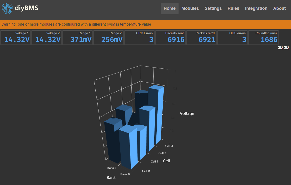
That case looks and sounds like a great fit for this. And that 3D chart looks pretty neat…
Personally I think the original layout was good, maybe because you are planning for the ES32, have the original layout, with only the voltages per bank, and leave the rest off the main screen, then have each Bank Voltage a click through to a detailed screen for that bank like the current home screen.
The packet sent and received and round trip could be very small and either added to header or in a small small block in the bottom right corner, the same text size for both options as the text size of the XY axis text.
The temperatures can be shrunk down or overplayed on top of the cell voltage bars in the same color but the outline white, or a slightly different color.
Just my 2 cents
Looks good Stuart. I have been trying to reach you. I am designing a BMS based on your work called FreeBMS. It will support a higher number of cells and have an interface through CAN bus. The modules will be connected through serial, but I am writing a different protocol. I love your work, it is much appreciated.
Hi Michael, interesting that you mention the features, I’ve just finished the code to support 256 modules, 16P packs and the serial protocol has been re-written!
The new controller I have also supports RS485 and CAN !
Hi Stuart, that is excellent news! If the software will work with my existing hardware (esp32 and diyBMSv4 Leaf boards) I might abandon my software and just make the FreeBMS a hardware only project. Will your serial protocol work in an electrically noisy environment? I also noticed some blocking code in the previous version where there is a delay for led blinking. Perhaps this could be improved using a timer library based on millis() and accounting for rollover? If your software proves to be reliable enough and can fail safely if necessary I would gladly use your code, it will safe me a lot of time. I look forward to reading your code.
Hi @EvlQuaker, I’d be grateful if you can point me in direction of the rogue “delay” routines, there shouldn’t be anything like that in there!
This is the experimental new branch containing the recent changes/improvements. Feel free to give it a whirl.
https://github.com/stuartpittaway/diyBMSv4Code/tree/256modules
The serial protocol is unidirectional and contains a 16 bit CRC check on each packet, electrical noise is difficult to cater for, but with twisted pair cables and optoisolators between modules, most people don’t get any problems.
Hi @stuart, I looked at the code again briefly and it looks like the worst delays are only used on startup in double_tap_green_led() and double_tap_blue_led() so those ones aren’t an issue. I also found 2 delays in main.cpp, 4ms to allow the voltage to stabilize before a reading and 10ms while waiting for serial. I know these seem pretty short, but if they are called in every loop it could interfere with timing critical code added later. I will read the code more thoroughly when I have time.
Thanks for showing me the new branch, I really look forward to trying it out. I just received the controller board I designed from the board house, so as soon as I solder a few components on I should be able to start testing 
What timing critical code are you thinking of adding?
The loop only runs when a data packet is received or the cell is balancing (or the WDT kicks in), interrupts are still enabled at this point to allow additional serial data to be received/processed by the ATTINY libraries, and the only thing the module does is drive PWM, which is all hardware based.
Once the first byte of data arrives on the serial bus, the module wakes up, takes a voltage reading, waits for 15 * 10ms to receive the serial data, then processes that packet and goes to sleep.
It sounds like the timing might not be an issue. I cant really think of any timing critical code that would need to run on the modules themselves. I haven’t had time to really dig into it yet, I have been away on a trip. Have you tested the new code yet? Is everything working well? Do you expect any issues going to the ESP32?
I’m currently running the new branch code (for about 2 weeks) no problems so far.
The ESP32 should be fine, I’m only supporting that on the new controller board as the old one has incorrect pin out for the header anyway. ESP32 DEVKIT-C is the board I’ve standardised on.