Samsung Mono HT Quiet (gen. 7) & MIM-B19N installation

Hi guys,

I’ve just installed MIM-B19N to this heatpump and wanted to ask more advanced users here if I’ve connected it properly. Found that gen. 7 has a different PCB layout and it has only one board. But I’ve tried to connect is as best as I could so hopefully it’s correct (modbus terminals are not yet connected). It didn’t blow up and it’s powered and greed light is blinking. Also was interesting there is no dedicated space where I could fit it so I’ve stich it with some double tape on the left side.

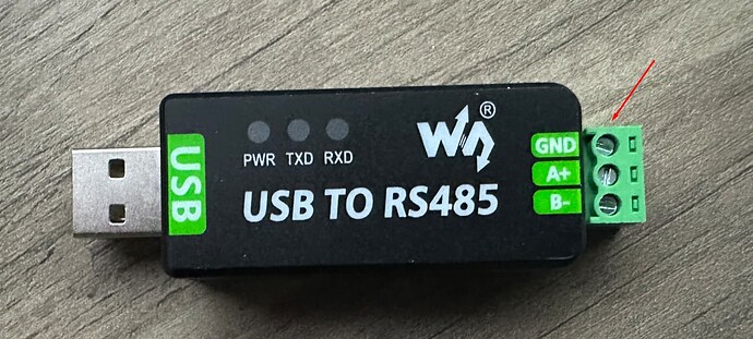
Also wanted to ask if I need to connect GND on RS485 to USB converter and ground on an outdoor unit ? Is it necessary ? Can I keep it not connected and connect only 2 wires to terminals A+, B- ? I’ve looked and communication cable which goes to control kit is not grounded either.

Additional question. Do I need to add terminating resistors 120 ohm on both ends or will it work without ? Don’t have any atm.

Thanks!

It depends. RS485 is really a 3-wire interface, A, B and GND. The GND connection is really a voltage reference for the A and B signals, rather than an Earth. However, with equipment that is mains powered and close together the GND is often connected to Earth, so does not require an explicit third wire GND connection.

If you plug your USB converter into a desktop PC, then the chassis and 0V of the PC are connected to Earth, so you can get away without an explicit GND connection. However, if you plug it into a laptop or anything powered by a wall wart, then these systems are isolated from Earth, and it may or may not work without an explicit GND connection (depends on leakage paths present). In this case you are better off connecting the GND explicitly.

For bus lengths of a few metres you can get away with no terminating resistor. But for more than that up to several tens of metres a single 120R resistor will be fine, and also improve the noise immunity of the link. Only when you get to hundreds of metres do you need terminations at both ends of the bus.

2 Likes

@rupert might be able to contribute to this.

  1. Wall warts - a power supply with a built-in plug top; UK wall warts have a three pin uk plug. They are mostly (all?) all double insulated; they should have the double insulated sign (square within a square) on the label and a plastic earth pin on the plug. As they have no earth connection, the DC power output is isolated from ground, and is floating at DC.

  2. Laptop style power supplies are generally power supplies with a separate cord set (mains lead and plug). They may have a two pin (C7/8 figure 8) or three pin (C13/14 IEC, C15/16 Kettle, C5/6 cloverleaf) connector on the power supply body, that the mains lead plugs into. For more information on the connector types, see
    IEC 60320 - Wikipedia

If the laptop psu has a double insulated sign or a two pin C7/8 connector on the body, then it will have no earth connection, so again the DC power output is isolated from ground, and is floating at DC.

I have three laptop style power supplies with no double insulated sign and C13/14 connectors on the power supply body. The mains earth is connected to the negative side of the power output on these, and so the DC output is not isolated from earth. One is a 12V supply for an old LCD monitor, the other two are 19V output for laptops. So care in identifying a laptop style psu is needed.

  1. RS485
    I don’t have any experience of using RS485.
    Information on RS485 is available at:
    RS-485 - Wikipedia
    https://www.ti.com/lit/an/slla272d/slla272d.pdf

Quoting Wikipedia:
In addition to the A and B connections, an optional, third connection may be present (the TIA standard requires the presence of a common return path between all circuit grounds along the balanced line for proper operation)[29] called SC, G or reference, the common signal reference ground used by the receiver to measure the A and B voltages. This connection may be used to limit the common-mode signal that can be impressed on the receiver inputs. The allowable common-mode voltage is in the range −7 V to +12 V, i.e. ±7 V on top of the 0–5 V signal range. Failure to stay within this range will result in, at best, signal corruption, and, at worst, damage to connected devices.

Care must be taken that an SC connection, especially over long cable runs, does not result in an attempt to connect disparate grounds together – it is wise to add some current limiting to the SC connection. Grounds between buildings may vary by a small voltage, but with very low impedance and hence the possibility of catastrophic currents – enough to melt signal cables, PCB traces, and transceiver devices.

I don’t know if a domestic installation would have problems with ‘disparate grounds’ - perhaps @Robert.Wall could comment on this?

So if a RS485 to USB converter is powered directly from a floating DC output, the G reference will not be present at both ends of the RS485 connection. This will also apply if the converter is powered indirectly from a floating DC output i.e. via a Raspberry Pi, unless something else plugged into the Raspberry Pi provides a ground.

Note that if you are using a emonVS, I think that the mains input lead provides an earth connection which is connected to the 0 volt line on the emonTx4/5 or emonPi V2, so this will provide a ground reference (assuming that the emonVs versions that come without a 3 pin plug have the earth wire connected to the right place!).

Apologies in advance for any blunders!

1 Like

Hi guys, thanks to all for inputs. At the end I was successful to establish communication between HP and Raspberry Pi with HASSIO installed. Communication via HA modbus interface (thanks to @glyn.hudson and ZimKev)

Now I would share some findings I’ve observed. Maybe it helps someone.

  1. The connection of Modbus controller to the pump was correct as shown on first picture.
  2. I’ve used twisted pair 0.8mm cable. I did not connect ground at the pump. Only connected at the other end (USB dongle) to the GND terminal. This probably has no impact and is probably not needed since Raspberry pi is connected to USB adapter so I doubt it is grounded. In any case communication works just fine.

This is sensors output with extra modbus registers (again thanks to ZimKev). Seems most of them works but for some I have some doubts. Can anyone say what’s wrong with that ?

First the outdoor FAN speed is not working. Shows 0 rpm while obviously it’s running. Controller room temp shows always 11.5C so not sure what is that. Defrost Operation shows some strange value, does anyone know what is it ? Eventually does anyone have working addresses for these ?

Thanks for insights.

Michael

The ground (safety earth) connection should never carry any current, so in theory it should be at the same potential as the general mass of the earth everywhere. However, during fault conditions the earthing system could be carrying a significant current - limited not by the fuse or breaker rating but by the fault level of the supply and the resistance of the cables involved. So there could well be a significant but short-lived (but not that short - a few half-cycles) voltage spike between two places.

Can you share the additional modbus registers, I would be interested in these also.

You may have a look here: