I don’t see how this fits with Ian’s comment. I have double checked by looking at Ian’s flow rate. On 28th March at 15.28 his flow rate is 28.3 L/min and at 17.08 it is 14.6 and at 21.12 it is 13.1. The flow temperature was never above 36C.
Just because the flow rate has gone down doesn’t mean the pump has slowed down it maybe zones have shut down resulting in more system pressure resulting in less flow from pump
Unless obviously they have a completely open circuit
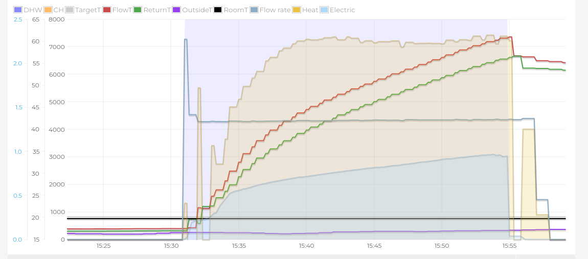
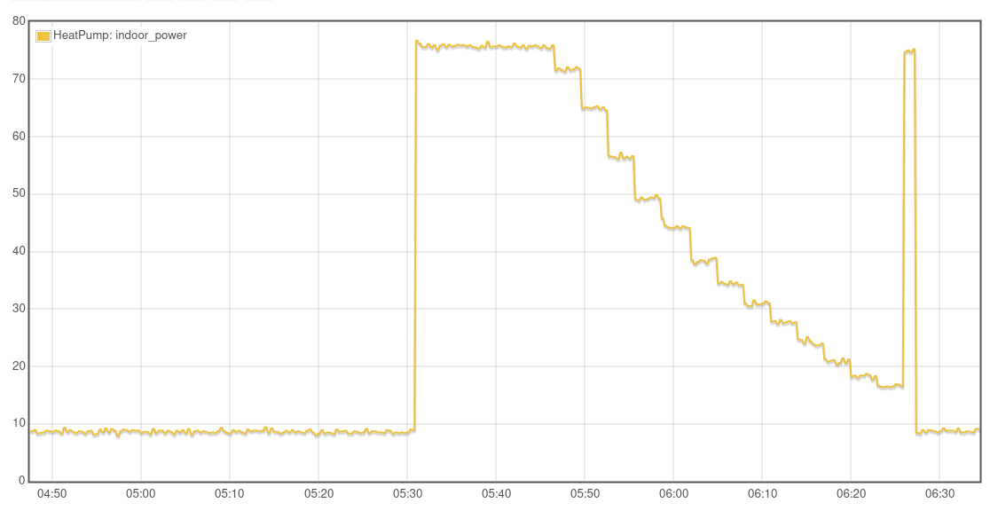
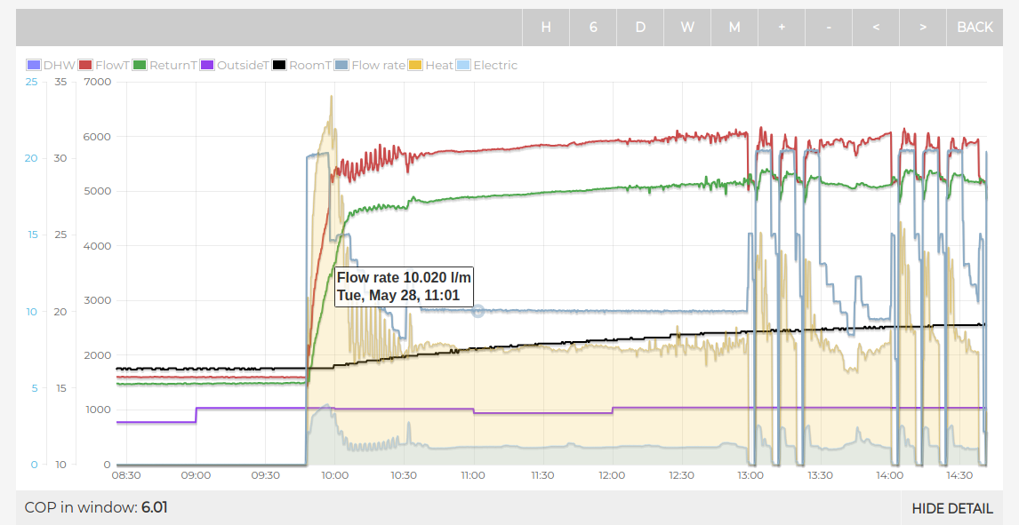
The system is completely open loop, there are no zones or valves to close. The flow rate in the graphs is the actual flow rate resulting from the pump slowing down. (You can hear the water speed reducing as the flow slows.)
And here is the power to the indoor unit showing reducing power input as the pump speed reduces.
Interesting discussion.
I took a look at the MIM-C02N outputs from a a couple of recent test runs. (I have FSV #4052 at the default 5degC even though my circ’n pump is fixed speed.)
Nick K is correct that the controller PWM output stays at 100% on DHW.
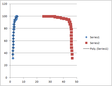
He also (almost) correct in saying that the PWM signal is 100% below an LWT of 45degC. Take a look at this graph (red line):
The x axis is LWT (degC); the y axis is PWM output signal (%).
OK it’s not quite as black and white as Nick suggests, but (by calibrated eyeball) I’d say the signal is still 95% at up to 45degC LWT (but drops like a stone above that).
3. The blue line is actually PWM output signal against (LWT-RWT), though the scale I’ve used isn’t very helpful. But you can see that (as you would expect) PWM output drops strongly as deltaT falls (the raw data shows PWM=40% at deltaT of 2.0degC).
4. I’d conclude from this that if you are seeing measurable circulation flow modulation at a lower LWT than ~40degC, then something else is going on.
5. (opinion only) The only factor that I would expect to change circulation flow during a DHW run would be that of physical properties (density, viscosity etc) on pump performance. IMHO the Samsung controller is a pretty blunt instrument (much as I love it) and my search for sophisticated DHW algorithms has to date eluded me.
6. If anyone can explain what FSV #4053 does, I’ll offer a small cash prize. Nick K doesn’t know, and changing it seems to make b* all difference to anything.
Sarah
Robert Kerr at Samsung when I asked about it said it’s an equation factor that works with t1 and t2
Which I’m sure you will agree means absolutely bugger all.
I forgot to ask him what the equation factor was is it a multiplier or something else
Love to know as far as I can see as my emitters and also my hot water cycle drop below a 5 degree delta t my pwm pump is at flat out all the time anyway. Maybe due to my flow rate is about right for heat output which is more luck than judgement
That should have said do not drop below delta t of 5 therefore the pump doesnt need to slow down to allow more loss of heat resulting in bringing back to 5
Many thanks for that info, John, it’s really helpful.
It explains why I couldn’t see any relationship - I’d been assuming proportional only control, when it’s clearly (proportional + differential) control. Subtle.
A little (50 year old) knowledge is a dangerous thing…
It just shows if your emitters are sized correctly and you are always open loop then a pwm pump is not really needed as long as your flow and heat emmittance are right you should maintain a reasonable delta t
Although the Grundfos PWM UPM4XL isn’t any more expensive than some of the other non pwm pumps
Robert Keer is back from his holiday and sent this which ckears it up
Hi John,
The PWM control logic during heating (doesn’t apply to DHW, as that is fixed to 5K) is to have a:
∆T of 5K when the supply is between 25~45°C
∆T of 8K when the supply is between 45~50°C
∆T of 10K when the supply is between >50°C
This is only when the system is balanced at the optimal flow rate for the heat pump installed.
5kw 14.5l/min
8kw 26l/min
12kw 35l/min
14KW 40l/min
16kw 46l/min
The logic is activated in the FSV’s for an inverter pump (factory default) and starts evaluating 5 minutes after safety start, but after 20 minutes of an operating system.
Sorry for the late reply. I got my Grundfos pump from Midsummer Energy. It included the PWM cable. Be sure to check the model carefully, not all Grundfos pumps support PWM.
That’s not correct, on my Gen6 PWM will modulate the pump to maintain DT at any flow temperature e.g 30C
I don’t think this is true, I’ve observed PWM being active during DHW, it seems to modulate down to 17 L/min, without PWM my pump will run at 22 L/min.
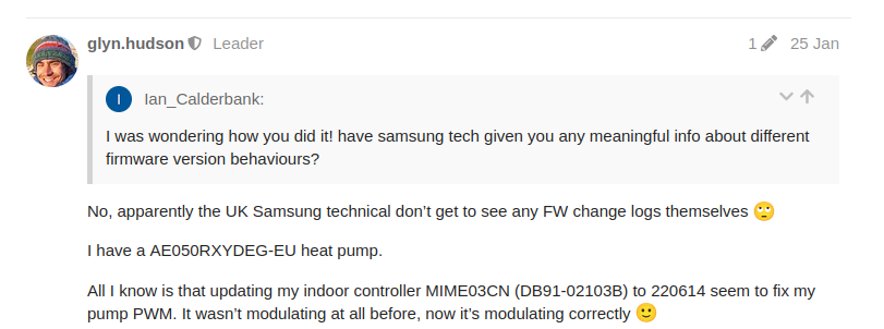
However, I did need to update my firmware to get PWM to work. The dataplate on my HP says it was manufactured in 2021:
For the first year I ran my HP without PWM, I’ve just come to the end of my 2nd year with the HP, this time with PWM enabled. This year I go a SCOP of 4.45 compared to 4.19 in the first year. I think PWM has helped with this 0.26 increase in SCOP, although it’s hard to say for sure.
Not sure if you see my last reply to Sarah from Robert Kerr at Samsung see below
Hi John,
The PWM control logic during heating (doesn’t apply to DHW, as that is fixed to 5K) is to have a:
∆T of 5K when the supply is between 25~45°C
∆T of 8K when the supply is between 45~50°C
∆T of 10K when the supply is between >50°C
This is only when the system is balanced at the optimal flow rate for the heat pump installed.
5kw 14.5l/min
8kw 26l/min
12kw 35l/min
14KW 40l/min
16kw 46l/min
The logic is activated in the FSV’s for an inverter pump (factory default) and starts evaluating 5 minutes after safety start, but after 20 minutes of an operating system.