I have a basic grid tied PV system with a Fronius 3.5KW IG Inverter that I had installed 8 years ago that has been working extremely well with Robins mk2pvrouter diverting to the Immersion and then to a secondary wirelessly controlled load. Excellent work Robin !
In March I had the system expanded with a Fronius Primo Gen24 6KW which uses a Fronius smartmeter to monitor export and comply with the regs to enforce export limit. This has all been working very well. I have also added Home Assistant control of smart relays to use the excess power above what the diverter could cope with feeding to storage heaters. This was all still working extremely well too until yesterday…
The batteries that were on back order were installed yesterday and now the immersion is drawing power all the time (pulsing) until the thermostat trips then it feeds power to the storage heater depleting the battery levels even at night.
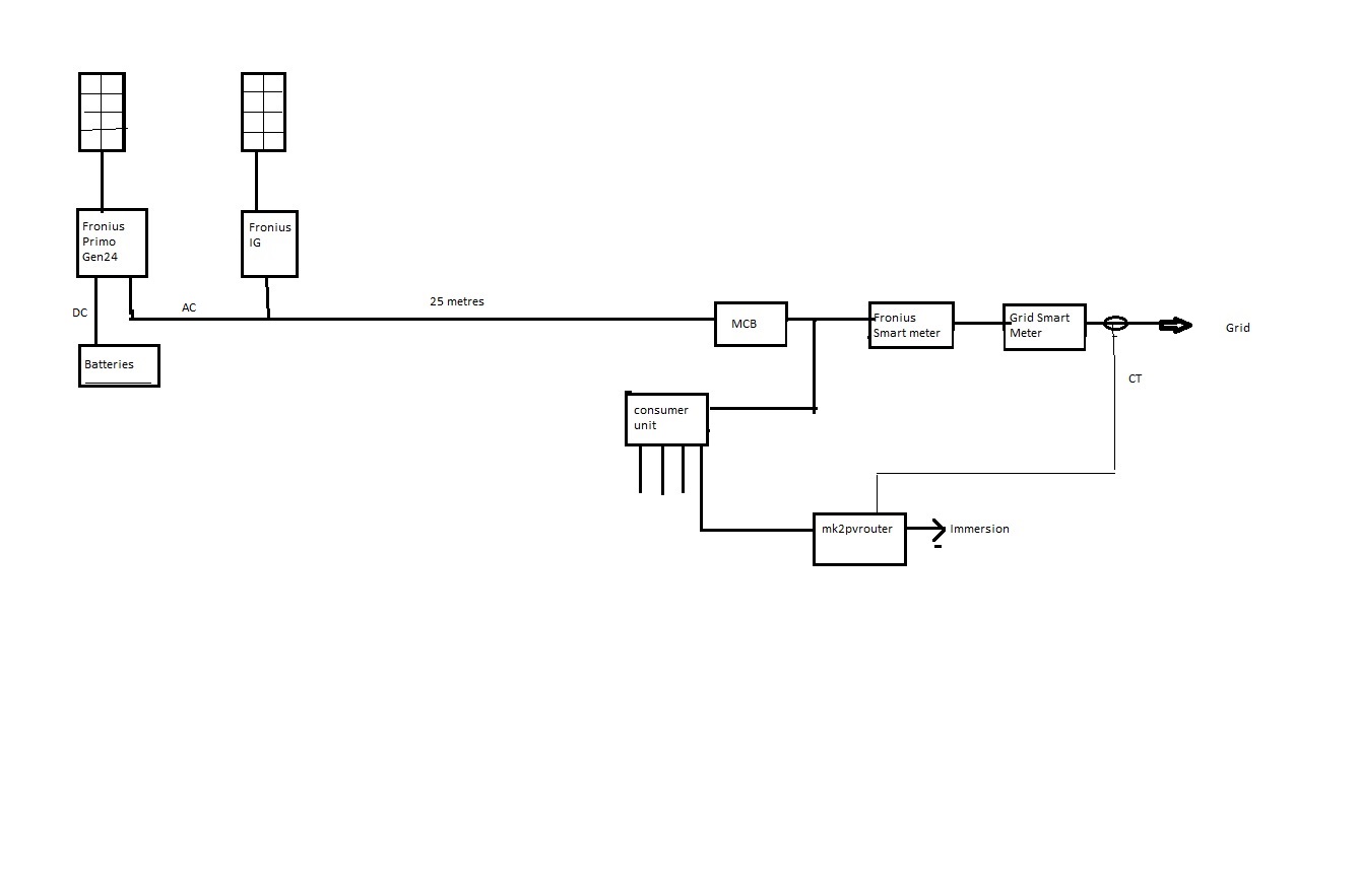
The CT for the mk2pvrouter is on the grid side of the smart meter but the Fronius smart meter is a sealed box with integral power monitoring so there is no possibility of passing the immersion load through a CT.
I am hoping there may be a simple setup I have missed and that someone has been here before but I do worry that I might be pioneering with this one. Help !!
Fronius will no doubt recommend an Ohm pilot but I really want my open source solution to continue working.
I have yet to find out how my dynamic loads are going to behave but at least I have the ability to factor in the battery state into the Home Assistant control so I hope this is going to work.
I think I need a single line diagram of your system (like the diagrams in the Using Multiple Diverters article) showing how everything is connected and where all the monitoring points for the various controlled items are.
Robin’s Mk2PVRouter aims to balance to nett zero energy flow (while it can, naturally) at its monitoring point (its c.t.). Everything downstream of that it considers to be house load (including its own load). Your problem is Robin’s Mk2PVRouter can’t tell the difference between PV and battery, and the Fronius meter has been installed so the two control loops overlap - it should be downstream of the immersion feed. You need to decide the order of priority, and then you/we need to figure out a way of straightening the system out again.
Hi Robert, Thanks for responding.
Yes, agreed the PV Router needs to know the charge / discharge state of the batteries in the decision making. Within my Home Assistant part of my system I have now incorporated using this battery status from the Fronius in order to decide whether I should be switching on or off the storage heaters and this is beginning to work OK. I will attach a rough diagram below but I think a more complex solution than moving CT’s or cables is needed. The Fronius Smart meter is part of the DNO approval so can’t be changed and I wouldn’t be happy anyway rewiring anything between the consumer unit and the grid where it can’t be isolated.
I think I need to be able to tell the PV router the battery state or be able to control the Inverter to prevent battery discharge while the PV is generating a reasonable amount but that would also need the PV router being prevented from turning on at night or low PV power. My thoughts are tending towards needing to add more comms capability to the PV router so that it can be told this information either via RF or Wifi with an ESP device as part of my Home Assistant system. Or am I over complicating it?
Incidentally I do have EMonTX, EMonBase and EmonCMS running alongside all this.
You didn’t say you had two phases! It’s getting really complicated. Robin’s router will only ever balance the one phase.
I take it the battery charger/inverter is the Fronius Prime, and the connection to the battery is d.c.
Can you get charging/discharging information from the Fronius? If you can, then you inhibit the Mk2 when the battery is discharging. This will mean the immersion is never on (unless you manually override it) while the battery is feeding or topping up the house or the grid. That should allow the Fronius system to operate as intended, and I think that’s all you need to do.
I think that’s the way to go. Robin (@calypso_rae) should see this and chip in.
When my meter was last swapped, I put an isolating switch in. The outgoing terminals of that are not sealed, so if I need to add Henley blocks and take a feed separate from the rest of the house, I can.
Sorry, in my crap diagram I was trying to show the live and neutral separately in the grid side of things as they are physically single core and to show that the CT was only round one of the wires, I clearly failed !
Yes the Primo is directly DC coupled to the battery pack which is good for efficiency but less easy to peek at what is going on without obtaining the info from the inverter Datamanager. I am able to select the charging to be just the DC, also from the IG via AC through the Primo or from the Grid (I would only want the latter if on Octopus Agile).
I am able to get the charge / discharge rate from the inverter in Home Assistant but what way would you recommend as the simplest for getting this information to the PV router?
Ideally I would prioritise the immersion as top so that we get hot water in the mornings and then the battery topped up in the middle of the day. I think maybe I need to ask Fronius if there is a way of preventing the Inverter from discharging the batteries for a period of time or, say, if the PV is generating more than ‘x’ then don’t discharge.
I’m happy with quick & dirty to begin with as I 've only been manually switching the immersion for 3 days and it’s already tiresome trying not to deplete the battery or use from the grid.
As the installers had to provide a diagram of the system to the DNO to gain approval I think that the Fronius smart meter has to be between the grid smart meter and the consumer unit or any other devices so my hands are tied there. The installers have to come back sometime to implement full house back-up as that is on back-order like so many things, so I could enquire if any adjustments are allowable.
Eon also have to return to try and fit the ‘smart’ meter properly so that it works rather than just hassling me for ages to have one fitted, fit it as a dumb meter then disappear because they have ticked the box saying ‘smart meter fitted’. OK it has the benefit of me being able to read the export but that is it. (rant over). So I could ask them for an isolator I guess. It has always surprised me that the only isolator is in the consumer unit but I suppose that’s historical.
I asked for a single line diagram. You DON’T show neutrals or earths on those. I think you need to edit it, or it’s going to confuse people.
That bit was missing.
In this case, you need the Mk2 to send a “permission to charge the battery” signal to the Fronius when there’s a nett outflow of energy it can’t balance, i.e. its “energy bucket” is full. You’ll still need the Fronius to signal “Battery Discharging” to the Mk2 to inhibit diverting energy to the water heater.
What does that imply?
I just bought it over the counter and said to the wireman “can you put the meter tails into this?” and he did. Yours would probably need to go downstream of the export meter because they wouldn’t trust you not to infeed upstream - and of course you need protection (i.e. a second consumer unit) if you put Henley blocks in to split the supply.
I haven’t looked into being able to control the Fronius from HomeAssistant just monitoring so, I certainly need to look at this.
The full house backup I mentioned is effectively using an approved method of switching the whole house to backup power in case of a grid outage. Obviously has to prevent power output to the grid so has to be certified and no DIY solutions. For me it’s the icing on the cake bit of the system design but the Fronius solution hasn’t been fully released so I have to wait. Other solutions are available but seem unreasonably large and clunky to me, not really designed for a home.
The ATMega 328P is a processor. What do you really want? Robin’s Mk2 PV Router might have spare digital I/O pins, depending on the PCB version and the facilities offered, there’s always the serial port (bi-directional) but whilst the radio is OK transmitting, I’d have doubts about using it to receive, because it would probably hog the processor too much for the energy calculations and diverter to work properly.
As I see it at present, you need two DIO pins available on the diverter. One an output to give the “bucket overflowing” indication, and the other an input to inhibit the diverter. If your add-on can accept/provide those signals, then it’s essentially independent. The output voltage of Robin’s diverter depends on which version you have - he’s used both 3.3 & 5 V. The particular ESP8266 that “The Shop” sells is I think 5 V tolerant on its inputs - if not, a simple resistor divider solves the problem. Even at 5 V, the '328P input is fine with 3.3 V logic levels.
A contactor with positively driven make and break contacts, 2 poles and a minimum 3 mm air gap is really all that’s required.
My initial thought was for a second wifi connected processor to signal to the 328P but then the idea of upgrading the processor came to mind as a possibility. In broad functional terms I think an ESP8266 is compatible with the Atmega328P but with the addition of wifi and fewer I/O lines so I thought I’d suggest the idea.
The Fronius Primo Gen24 is a hybrid inverter primarily for grid tie but can work off grid. The AC outputs are the same for grid-tie and off-grid so it’s not just switching the grid connection off and connecting a different generator output. The inverter has to be told which mode it’s working in and also if in the off-grid mode it works at 53Hz so that other incompatible inveters, such as my IG, do not output. But I am digressing with this thread.
If you’re thinking of energy measurement with an ESP8266, forget it. It has nowhere near the 328P’s capabilities in that regard. I was thinking of it as a WiFi interface for Robin’s Mk2 - if the latter has a pair of I/O pins that can be used.
My Mk2 PV Router sketches that were posted here (on the archived forum) have plenty of spare IO ports.
With the equivalent sketches on my own website Mk2PVRouter - Downloads, most of the spare IO ports are assigned to a 4-digit LED display which shows the daily total for Diverted Energy in kWh.
I was under the misapprehension that the 328P only worked at 5V. I have the Rev 1.1 of the main PCB so it looks like it’s 3.3V which makes things slightly easier.
If the most of the ‘spare’ IO ports are used by the LED display then I may have to forgo the display inorder to get a working system if there are no other spare IO’s?
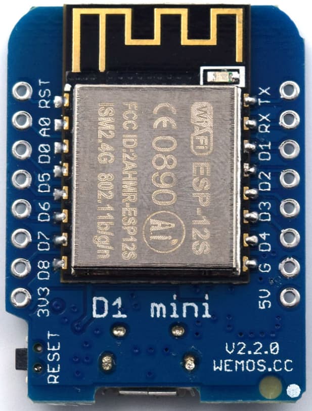
I am still wondering if it might be best to make a plug in daughterboard to replace the 328P with an ESP32 D1 mini. Surely this has the capabilities for running the Wifi on one core and the PV router on the other? It seems a bit more elegant than adding an ESP8266 in addition to the 328P and it is more flexible for further development if the initial ideas don’t work. I am no expert on the differences of the processors so am I wrong?
I don’t know the ESP32 D1 mini, what you need to look at is do you have two or three analogue inputs available, and what sample rate can you get when using two, ideally three if you want the diverted power/energy - measuring 2 currents & 1 voltage - in terms of sample sets per mains cycle. You are going to want at least 30 to have a reasonably accurate measurement when the current wave is distorted away from a clean sine wave.
Espressif analogue inputs had a bad reputation. I’ve read that these problems have been solved, but I can’t vouch for that.
I was thinking of the ESP32 D1 mini which has the WROOM processor module and has " Analog-to-Digital Converter (ADC) – Up to 16 channels of 12-bit SAR ADC’s."
Whichever you use, the criteria for reasonably accurate power measurement remain the same. If you can’t read enough points on a (most probably) distorted wave, then your energy balance is in jeopardy.