I’ve attached it to my multimeter to measure the current when a load is connected and I’ve worked out a number of turns of about 6500
I’m using an Arduino Nano to try and get the current; I’ve built the circuit with the voltage divider explined here Learn | OpenEnergyMonitor (using 2 10k resistors), 10uF capacitor and a 150 Ohm burden resistor
I’m using a 5V supply
I’m only trying to read the RMS current, I’m not interested in voltage or power factor at the moment hence I’m just using the following code
I’ve used the calibration value 1000 to make things more readable; what happes is that I read a value of arund 3 when no load is attached and 5 when a 42W load is attached.
This tells me that the RMS calculation is not functioning correctly
I have to fudge this by adding an offset
double Irms = emon1.calcIrms(1480)-3; // Calculate Irms only
This way the value becomes proportional to the load through the CT, but I don’t think I should be doing this, what is wrong?
That is not a useful number. What you need to know is the current ratio, i.e. the output you get at the rated maximum current of the c.t. For example, the YHDC SCT-013-000 that we use is described as 100 A : 50 mA, that tells me that the maximum current it can measure is 100 A, when the secondary current is 50 mA. Until we know the rated current, it’s hard to know what you should expect from your Nano.
You are almost certainly measuring electrical noise. It might be picked up if you long unscreened leads anywhere, but in our experience it is more usually coming in via the power supply that you’re using.
The calibration factor that you need in emon1.current(A7, 1000); is the current that gives you 1 V at your Nano’s input. When you calculate that, it will give you a better idea of the genuine error. When the 100 A c.t. is used with the emonTx, it’s usual to read about 100 mA of “noise” even when no current is flowing.
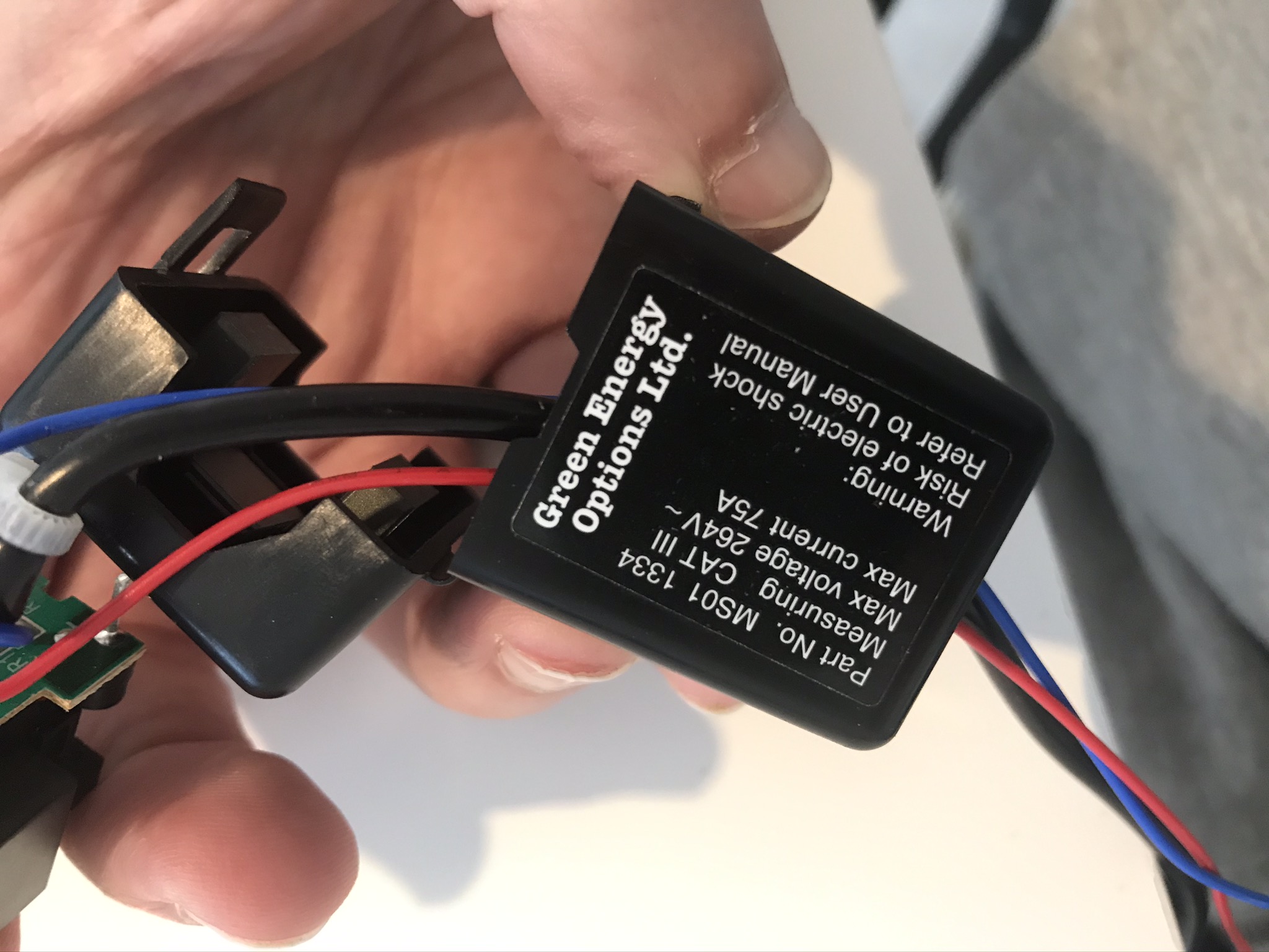
So it seems that your c.t. is really 75 A : 11.5 mA, which is a very peculiar number. With a 150 Ω burden, your calibration constant should be about 43. It looks as if you’ve designed for a maximum current of about 70 A.
Unfortunately there is no indication of the current ratio on the CT
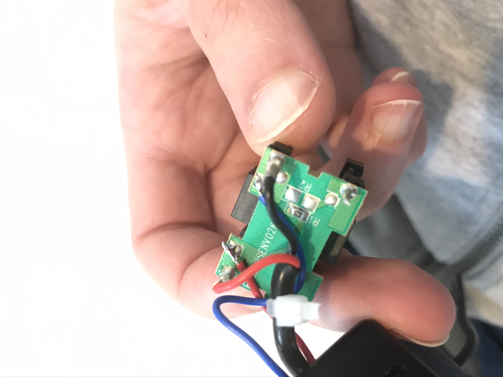
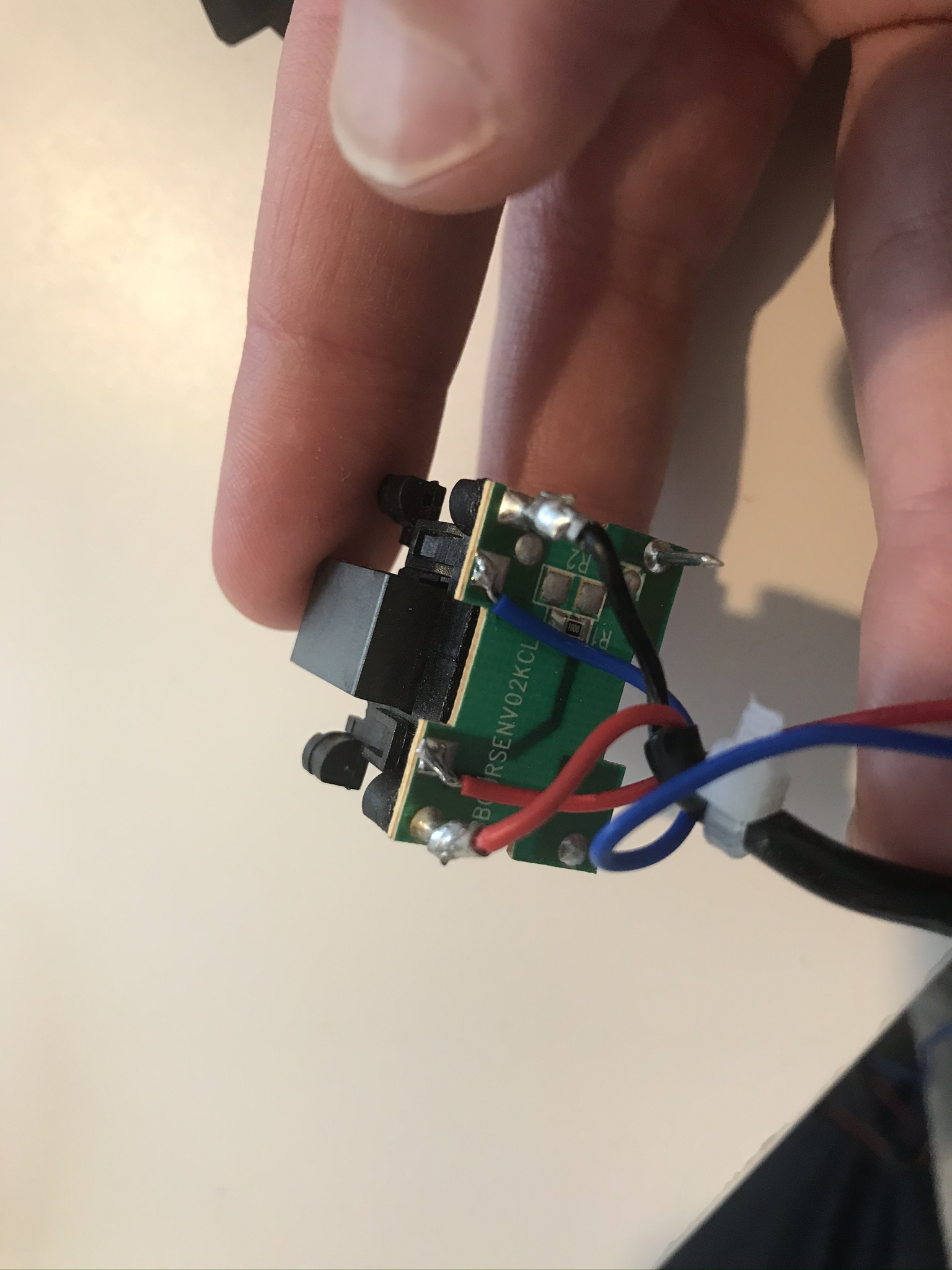
I see there is a small resistor inside (see pictures in first post), could this be a built in burden resistor?
I read 84 Ohm at the leads with nothing attached (not sure if this would be the value of that resistor or/and the windings)
I’ve tried attaching the CT directly to the Arduino (one lead to ground and one to the PIN 7) and running the code; now I do get 0 with no load attached and a higher value with the load ON… not sure if this is expected
Almost certainly. If you can read the value, that would help to confirm it. From the numbers you’ve given, I think 84 Ω is reasonable for the secondary winding and that resistor in parallel. That also explains why I am suspicious of your 6500 and the 11.5 mA that I calculated.
What you need to know now is the voltage that you get when 75 A is flowing. There’s an easy way to get 75 A - what you want is 75 ampere-turns, so a 1 kW heater is about 4.2 A, so if you wind a coil with 17 turns and clip your c.t. onto that, you’ll have in effect 71.4 A, which should make measuring the voltage easier. One possibility is about 0.333 V.
Of course, it might also be a zener diode [even though it’s labelled ‘R1’] to protect against over-voltage. Until the c.t. is tested properly, or we find some data, we won’t know.
That won’t be meaningful. You’ll only be measuring the positive half-cycles, and those not properly because the software filter in emonLib will set a false zero to it and treat it as the complete wave. You’ll get a very wrong answer that way.
But connecting it to the proper bias circuit without the 150 Ω is the way to go.
I have that problem these days with those components. A pair of pharmacy reading spectacles of about 3.5 dioptres is my solution.
Definitely a resistor then, so you should not have your 150 Ω as well - that only reduces the sensitivity and makes any noise worse, because the calibration constant must increase to to restore the calibration but at the same time it has the effect of amplifying the noise.
Yes, it does. So the secondary winding is about 525 Ω, which is believable, and a secondary current of 22.5 mA, also believable.
So, with a 5 V Arduino Nano, your maximum input voltage is 1.6 V rms (allowing for a little headroom, which makes the maximum current you can measure about 54 A. So I think that without the 150 Ω (which would put the max. current up to 90 A), you’re good to go.
The calibration without the 150 Ω will be 33.5 approximately (55.6 with). So the calibration you tried - 1000 - was in effect giving you an amplification (of the noise) of around twenty times.
If you still have a significant reading under no-current conditions, layout of your breadboard is fairly important, and as I mentioned, so is the quality of the power supply to your Nano. Some have found that using the higher input voltage and the on-board regulator gives a better result.
This might help: Noise in Arduino based builds. | Archived Forum
I think that’s absolute confirmation that you’re measuring noise + signal.
I’ve not encountered those, but if the count for the same voltage is 4 times, then it follows that you must adjust the maths to suit. If you go through the code of emonLib, you’ll find the ADC_COUNTS constant is part of the calibration.
There is also an additional problem using the TTgo (which I need to use eventually as I want to report the reading via wifi):
When I read (Using analogread() ) the mid point of the voltage divider with the Nano I get 512 (1024/2), but when using the TTGo I read around 2600 (while I should be reading 2048), so there is some non linearity in the voltage reading
Is it non-linearity, or an offset or scale factor? The first is bad news, the second and third you don’t really need to worry about, because the 552 will be taken out by the software filter in emonLib, and the scale factor can be taken out with calibration.
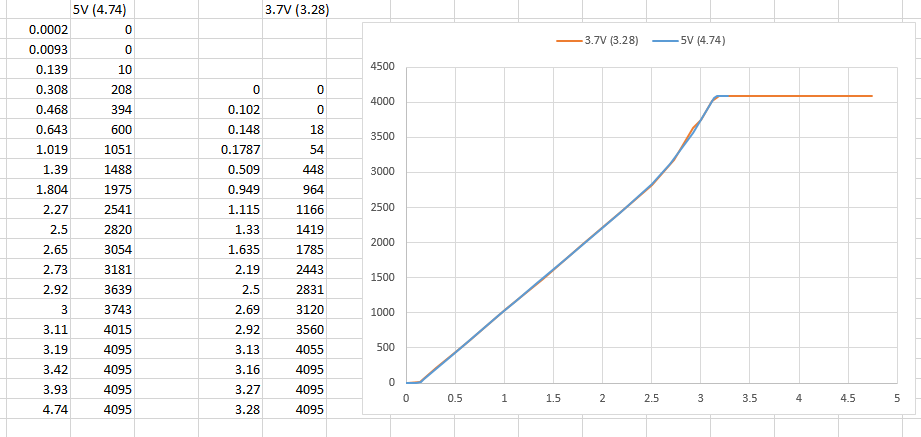
If you can measure a handful of d.c. voltages and plot them, you should see what the situation is.
That is excellent information, but sadly the result does not look good. You were absolutely right, it is non-linear. It is OK to about 2750 counts, above that it’s best avoided.
The offset at the bottom will disappear through the action of the filter in emonLib, we can forget that.
For best accuracy with that ADC, you should set the bias voltage to mid-way between 0.14 V and 2.5 V = 1.32 V, then you’ll need to adjust the calibration because 2.36 V = 2820 counts.
Because you are using only part of the input range, and depending on the maximum current you need to measure, you might also need to add a second burden resistor to reduce the c.t’s output voltage to no more than 2.36 V peak-peak. That too will mean adjusting the calibration.
Should I take voltage measurements again with the proper power source connected (it’s connected to my laptop usb port at the moment, but I’ll be using a different source when in use)?
Is it always necessary to measure the effective power supply and not assume it’s exactly 3.3V even if perfectly linear?
I think you need to check that the result is much the same. You are really only interested in knowing where the linear region is. That is the TTGo that you’re going to use - the graph is telling me that it was either working off a 3.3 V supply, or it’s analogue reference is 3.3 V.
If the supply you are going to use is close to 3.3 V, it is probably not worth measuring it again.
If the power supply is the reference voltage that the ADC uses, then yes. But usually, there are other factors that affect the calibration as well as that, such as resistor tolerances and the c.t’s manufacturing tolerance (and no, they don’t always have exactly the same number of secondary turns), so that it’s necessary to adjust the calibration to compensate for the combined effect of all those things.