Hello everyone. My first post here, total newbie to the emonPi / open energymonitor world.
My Pi, 6 x DS18B20 sensors and RJ45 terminal block breakout arrived this morning and I’ve been getting it all set it to test it.
I’ve been able to add each of the 6 sensors to emoncms as t1,t2,t3 etc but I’m not sure how the numbering relates to the breakout block. For example, is t1 = the sensor connected to the lower left of the breakout board, t2 middle left, t3 top left, etc?
I will be using the sensors to monitor different parts of my heat pump / underfloor heating system, so will eventually want to name each input something like ‘flow’ , ‘return’, ‘outside air’, etc but obviously the first step is to know which one is which in the cms.
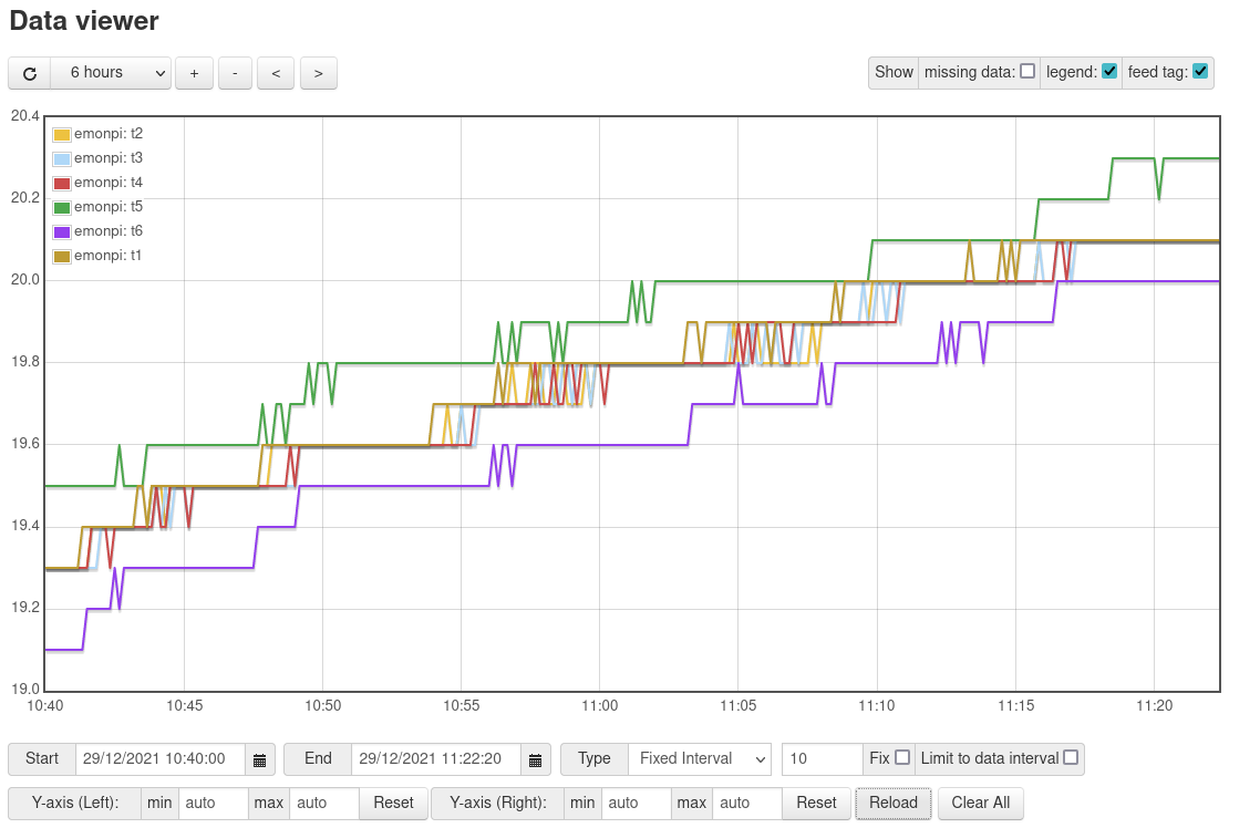
Also, as a test I’ve placed all 6 sensors in to a cardboard box and left them logging for 30 mins or so. Is the variance between t6 and t5 (purple and green) of around 0.3deg within the expected tolerance?
For a long and full explanation, read up in ‘Learn’ the two articles on temperature sensing. For the shorter version, all the sensors get their instructions and report their data on a “One-Wire” bus – which in fact is three wires, GND, Power and Data. The order the sensors pop up depends on their serial numbers programmed in by the manufacturer, but that relationship is complex. The second article explains it.
There are two things that you can do: either heat one up in your fingers and see which responds, or connect them one at a time to a test sketch that interrogates the serial number, write that down and then plug that number (permanently) into the sketch inside your emonPi. You’d need to rewrite the sketch in your emonPi for that. More reading: emonLibCM (which the emonTx uses, the emonPi doesn’t as yet) can accept a list of serial numbers, and then each sensor is guaranteed to end up in the same position in the list. If you allow the sketch to search for sensors each time it restarts – the default and the position with the emonPi – then if one is missing, the order will shuffle.
The spec. for a bona-fide Dallas sensor is ±0.5°C between -10°C and +85°C, wider outside that range, so yours are within spec.
I think I’ll start with the simple ‘finger warming’ method for now then, as I’m a newbie to all this. Although one potential problem I see with this is that If I set up the emonPi with the 6 sensors now, and then decide to buy another breakout board and add an additional 6 sensors, it sounds like the positions will all change and I’ll have to work it all out again. Which could be a pain if the original 6 have been fixed to the pipes by that point.
Is there a simple guide that explains how to ‘rewrite the sketch in your emonPi for that’?
Also, is there a maximum number of temperature sensors supported by the emonPi? I see the emonTx is limited to 3, but see no mention of limits on the emonPi page. Thanks.
Unless/until you preserve the sensor addresses within the sketch, that’s a certainty. It’s also a certainty if one breaks in any way, and needs to be replaced.
Unfortunately not. If you’re up to the task, the way to go is to remove the code that searches for the sensors, and (manually) fill the array of addresses that it filled by searching with the sensor addresses with the addresses you know. If you only have an emonPi, that’s going to be moderately hard and very fiddly. You might be able to do it by editing and compiling the sketch on the Pi, and working through the Admin page and Serial Monitor of emonCMS, but the way I’d do it is disassemble the emonPi and use a programmer and USB power supply on the “emon” shield in isolation, connecting directly to a laptop using the Arduino IDE to compile and update the Atmel ATMega 328P directly.
As the software stands, it’s 6. But you also need to change emonhub.conf to accept the data from more sensors. The problem you might face is the time it takes to read a sensor, obviously double if you go from 6 to 12. That shouldn’t be a problem, but I don’t have access to 12 sensors, so I can’t prove it.
Looking at the sketch, the file is ‘temperature.ino’ . That’s where you’d need to (hard-code, or maybe use the EEPROM) store the address array, There’s a debug statement in the code to extract the address. So you need to use that, then make changes.
(The emonPi software is here: https://github.com/openenergymonitor/emonpi/tree/master/firmware/srcNOT in Atmega 328.)
And if you do need to replace a sensor, it’s a repeat (at least partial) of the procedure, unless you add in a way to write the new address into EEPROM and read it from there, stolen from the latest emonTx sketch that can do this.
Not I fear an easy task, whichever way you look at it.