Hi
I’m heavely struggeling adapting the RFM69CW library from Jeelib on a ATmega2560 to work together with a Standard emonPI on raspberry PI3. The base of the HW and SW design is emontxV3.4.
I have an custom made ATmega2560 board with an RFM69CW 868MHz (connected over and voltage Level converter 5V/3.3V)
So the problem is that the ATMega is not sending any data over the SPI bus to the module. The Pins SS=Pin53, MOSI=Pin51, MISO=Pin50, SCK=Pin52 and SS=Pin2 are not changing. I’m using Arduino IDE 1.6.12.
I set up the correct ATMega2560 CPU in the IDE.
I’m using the commands from the library jeelibmaster:
#define RF69_COMPAT 1
#include <JeeLib.h
#define RF_freq RF12_868MHZ
rf12_initialize(nodeID, RF_freq, networkGroup);
rf12_sendNow(0, &emontx, sizeof emontx);
Here is my test code:
#define RF69_COMPAT 1        // using RFM69CW
#include <JeeLib.h>          // https://github.com/jcw/jeelib
ISR(WDT_vect) { Sleepy::watchdogEvent(); }
const byte LEDpin=                 41;      // Test LED Pin of ATmega2560 custom plattform
//-------------------------------------------------------------------------------------------------------------------------------------------

//-----------------------RFM69CW SETTINGS----------------------------------------------------------------------------------------------------
#define RF_freq RF12_868MHZ   // Frequency of RF69CW module can be RF12_433MHZ, RF12_868MHZ or RF12_915MHZ. You should use the one matching the module you have.
byte nodeID = 8;              // node ID
const int networkGroup = 210;

typedef struct {
  int power1, power2, power3, power4, Vrms, temp;
} PayloadTX;     // create structure - a neat way of packaging data for RF comms
PayloadTX emontx;

//-------------------------------------------------------------------------------------------------------------------------------------------


void setup()
{
  pinMode(LEDpin, OUTPUT);
  digitalWrite(LEDpin,HIGH);
  rf69_initialize(nodeID, RF_freq, networkGroup);    // initialize RFM69CW
  digitalWrite(LEDpin,HIGH);  // just for test
 /*
  for (int i=10; i>=0; i--)     // Send RF test sequence (for factory testing)
  {
    emontx.power1=i;
    rf12_sendNow(0, &emontx, sizeof emontx);
    delay(100);
  }
*/
 // rf12_sendWait(2);
  digitalWrite(LEDpin,0);
} //end SETUP

void loop()
{
  emontx.power1=5;  // test value
// rf12_sleep(RF12_WAKEUP);   // not used, HW has enough power and is always powered by source
   rf12_sendNow(0, &emontx, sizeof emontx);   // *SEND RF DATA*
// rf12_sendWait(2);
  delay(2000);
}
The rest of the HW works fine. I’m using a digital oscilloscope to see the Signals. I can see the signals when I’m programing the ATmega over USBtiny, but not when the HW runs by it self.
The ATmega2560 can write and read to the device. I tested this by sending and reading singe data to the RFM69CW.
I checked SPI the signals from ATmega2560 so that SS=Pin53, MOSI=Pin51, MISO=Pin50, SCK=Pin52 and SS=Pin2. The signals translations from the ATMega 5V to 3.3V RFM69CW are fine. So clear 5V signals resp. clear 3.3V signals ( 0 → 0V and 1 → VCC, no Offset).
See here the schematic of the RFM69CW Connection to the ATmega2560:
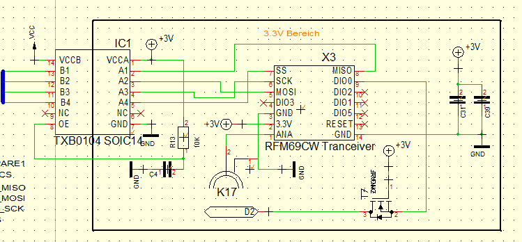
Many thanks for your help!