Hi does anyone know of a very simple way to construct a relay switching circuit that can sense when my grid feed is negative; i.e. when I’m exporting power to the grid? (on/off only, no detailed measurement needed).
I want to switch my power wall batteries to charge from mains when my house solar is feeding the grid, then stop charging when the panels are no longer exporting.
Batteries are located remotely about 40m away from the distribution board, and the only signal I have available is the CT sensor. My inverter correctly reads negative when I’m exporting, but somehow I need to grab this signal from the CT to switch a relay. Any ideas?
What does the c.t. connect to? This topic has “diyBMS” as the tag - if that’s all, then I’m afraid I don’t know anything about diyBMS, so I can’t help you.
I’m using this Bi-directional DC & AC Energy meter for some time now. At first I used it to switch on/off the charger but at that time i already knew this is not going to work as you need to have at least the same amount of negative energy measured as your charger is going to take before you switch on the charger otherwise the measurement will be immediately positive and your charger will switch off again.
So I moved to a different solution. My charger is now switching on at -50 watt (energy to net) at that point the chargers output is close to 0 amps. The moment the amount of negative energy measured is increasing the output of the charger is turned up in a way negative energy measured stay’s in between 0 and -50 watt. The moment energy measured flips to positive the charger will be turned down and switches off it at the lowest possible output current there is still a positive measurement of energy from the grid.
This worked reasonable well but the adjustments to the charger where to slow so at some points it took to long to keep in line with the measurements done at the grid side. This made me change the installation to a more dynamic way of steering the chargers output. Instead of operation always at the same speed now the speed is related to the amount of energy measured. This make a huge improvement.
But still there is a downside the inaccuracy of the measurement. So now I’m doing experiments measuring grid energy with a Carlo Gavazzi energy meter that has M-bus output. So in time I will change from measuring with a CT sensor to this device. The part at the charger will stay the same.
My setup is now:
CT sensor measurement
MQTT transmission to Node-Red
Calculation store measurements in SQL
MQTT to charger
Charger output being regulated
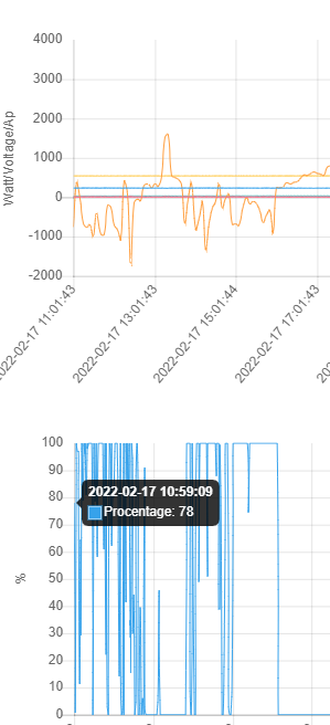
This is how measurements and charger output looks like.
Hi Albert, that’s really good, and very close to what I need (I too had also thought about the problem of when and how the DC charger would cut in).
But I think I might be stopped right at the first hurdle, as this system uses a hall CT, and I only have access to (what I presume is ) just an analog coil inside my CT. I’m guessing the hall CT’s output 0-5v dc?
I can’t change this CT as it’s only on a two wire twisted pair on a long run of about 40 meters, but also I need it to stay in place as it feeds inputs to other inverters too.
Maybe I could rectify the output from the CT and use that voltage somehow?
I’m using this kind of inverter in my system that has it’s own CT. The second CT is for measuring energy flows from/to the grid. The measurement and charger controlling units are talking over WiFi so the distance for this part is no issue.
But as I said the accuracy of measuring with the CT is for me not good enough. And using a device as I’m going to use now also solves the issue of distance and bad wifi signal. M-bus is working up to 1000 meters over twisted pair wires.
You’re missing an important point here: You need the voltage and current waveforms to detect the direction of power flow. It’s explained right at the beginning in ‘Learn’.
As @Albert says, if you can extract the information you need when the raw signal has been processed, that’s probably the easiest.
Peter has brought me to an idea. If we measure the energy at the distribution board in a digital form. For example with the Carlo Gavazzi energy meter, we can send the signal via network or M-bus to the location where the batteries/inverter is. Converting the digital measurement back to an analog signal can drive the charger and the inverter.
In my situation I’m already doing this and I think I can also drive the inverter by a just a analog control signal 0-20ma of a voltage. That would make the system also more reliable as the CT of my inverter is also not very accurate I see sometimes energy going into the grid when it is produced by the battery powered inverter.
There are other energy meters of course that will do the same job, but if you are measuring the grid connection, then you will almost certainly need one that can be used with a split-core c.t., rather than needing to be permanently wired in. The Peacefair PZEM series has appeared in these forums from time to time.
I do not prefer a Peacefair PZEM as it has no digital output, my preference is going to the earlier mentioned device. It is permanent wired but that doesn’t matter. Later in my country it will be mandatory to have a what is called smart meter that has a P1 port to extract data from then I will switch again but for the coming few years a permanent wired device is the only accurate solution with a data port. I still have a farrarismeter that turns backward when energy is going to the grid, for now this is economical the best thing to have.
Sounds very interesting. A remote sensor sent over ethernet would be a great way to go. Kind of reminds me of an old Owl CT sensor and remote ethernet box I had.
I als have one of these inverters and it have read somewhere that it can be controlled without the CT. I will have a look at the possibility to control charger and inverter with just a single accurate measurement device
I will do. But are you in the UK not allowed to install a permanent wired meter in your distribution pannel? Over here in the Netherlands everything above the meter is the responsibility of the owner of the property. This doesn’t mean un-qualified people are allowed to do modifications but it gives us the ability to install our equipment of choice.
Likewise, an alteration of that nature - which will require breaking the seal on the meter - must be done by a qualified person. A meter that uses and external split-core c.t. And plugs in for the voltage does not suffer that (potentially expensive) limitation.
@Albert Apparently there is a remote limiter unit that these “Sun Gtil” inverters can hook up to. It must run over RS485 or something. I dont know much about it; there are two inputs one is ‘internal ct’ the other is ‘external ct’ (the remote unit). Thinking about it, it’s just a two wire input on either of those ct inputs.
@Bill.Thomson This also is using a CT sensor, that is just what I don’t want. @Robert.Wall Over here no seals have to be broken to install a permanently wired meter. Here in NL you have the cable come into your home the first box it enters is a mains breaker box. There are different boxes some have old fashion fuses others have manual switchable fuses. Usually right above the mains breaker box the energy meter is found. Both the main breaker box and the energy meter are sealed you are not allowed to work on them. If you have a mains breaker box with old fashion fuses the first device you find in the distribution box is a mains circuit breaker that is also used as main switch. After the main switch you find the earth leakage circuit breaker(s) and after them the circuit breakers of the differed groups in the home. The Distribution box is not sealed and qualified people can work on everything that is inside it. I would put the permanently wired meter in between the mains circuit breaker and the earth leakage circuit breaker(s). I don’t know the situation in the UK.
@artypete The Sun GTIL inverter has two inverter inputs (internal & external) the internal only works with the CT clamp that is only a option when relatively short to the breaker box. The external input can work with a external limiter, I have looked into the original external limiter it is also not an option as I don’t think you can power the complete home via this unit.
The signal that is coming from the external limiter is looking to be an PWM signal but it is not. If the signal goes low the inverter will ramp up, the moment the signal goes down the inverter is ramping down. There is no point where it stay’s stable so it is always going up or down. Switching the signal up and down rapidly will keep the inverter output roughly at the same output. This basically only works if you do rapid measurements and constantly send the results to the inverter. Over a network this not a real option.
I also found information about the ability to connect a potentiometer to the inverter with this potentiometer you can smoothly regulate the output power. This could be an option by rotating the potentiometer with a stepper motor turning up or down and send the controller a Up/Down/stop signal this way the measurements can have a slower interval. It is just finding the best equation between rotation speed and measurement interval.
There seems to be a downside on using a potentiometer, I found people reporting the potentiometer break down due to the amount of current going through it. There are also people trying with a digital potentiometer but I expect the same issue an other problem with these digital potentiometers is that I never found one that doesn’t have one side of the potentiometer connected to the potentiometers supply (gnd or vcc)
I’m going to have a closer look on the potentiometer solution as it comes close to what I also do with my charger. Only have to look into the amount of current going through it.
This is why I cautioned you regarding giving specific advice to people in a different country. If you’d written “Here in the Netherlands, I am allowed to do this.”, that would be fine, but you can’t say that practice where you are is acceptable anywhere else.