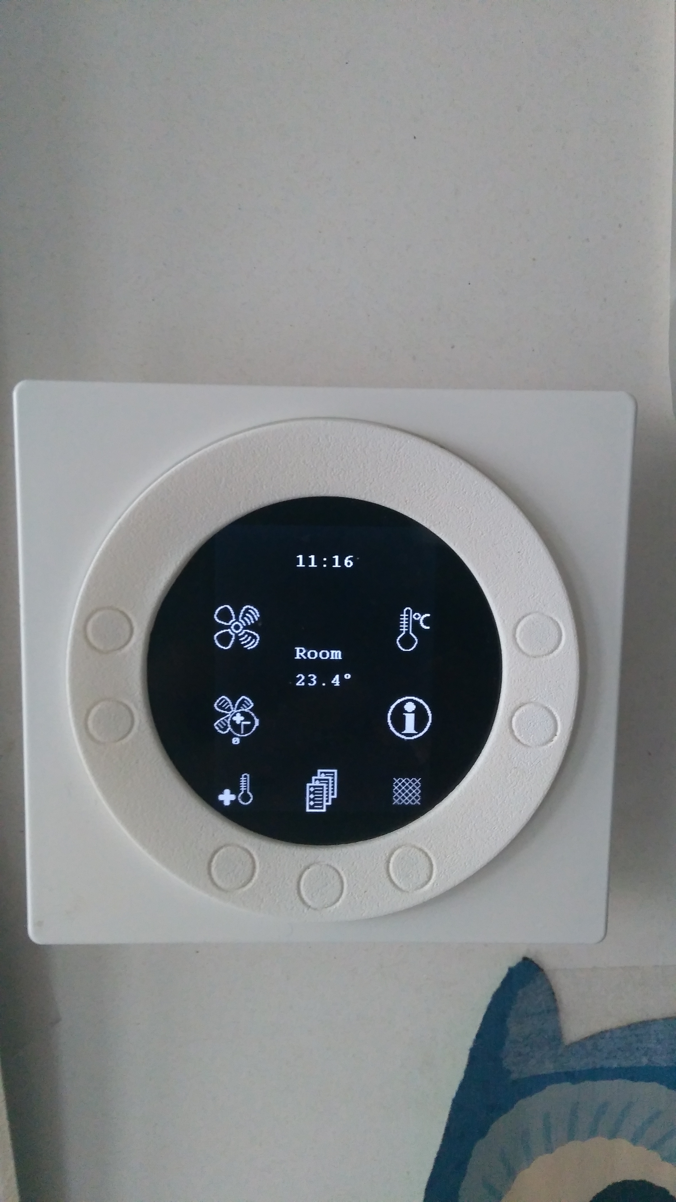
We’ve got a ‘Genvex Combi 185’ controlled by a ‘Optima 311Combi UK’. With an energy transition in mind, that controller will not be flexible enough. I can’t automatically control it. Eg. heating up domestic water when prices are low of when there is lots of sun.
Maybe there is a solution from Genvex itself and so EXCECON contacted them. Their answer was “I’m affraid that there’s no posibilities of doing so,” There is a “Genvex Connect”, but probably this isn’t compatible with my system, otherwise they would have suggested it.
I searched the web for info on somebody who already made a custom solution. I found this and this, but nothing for our Genvex .
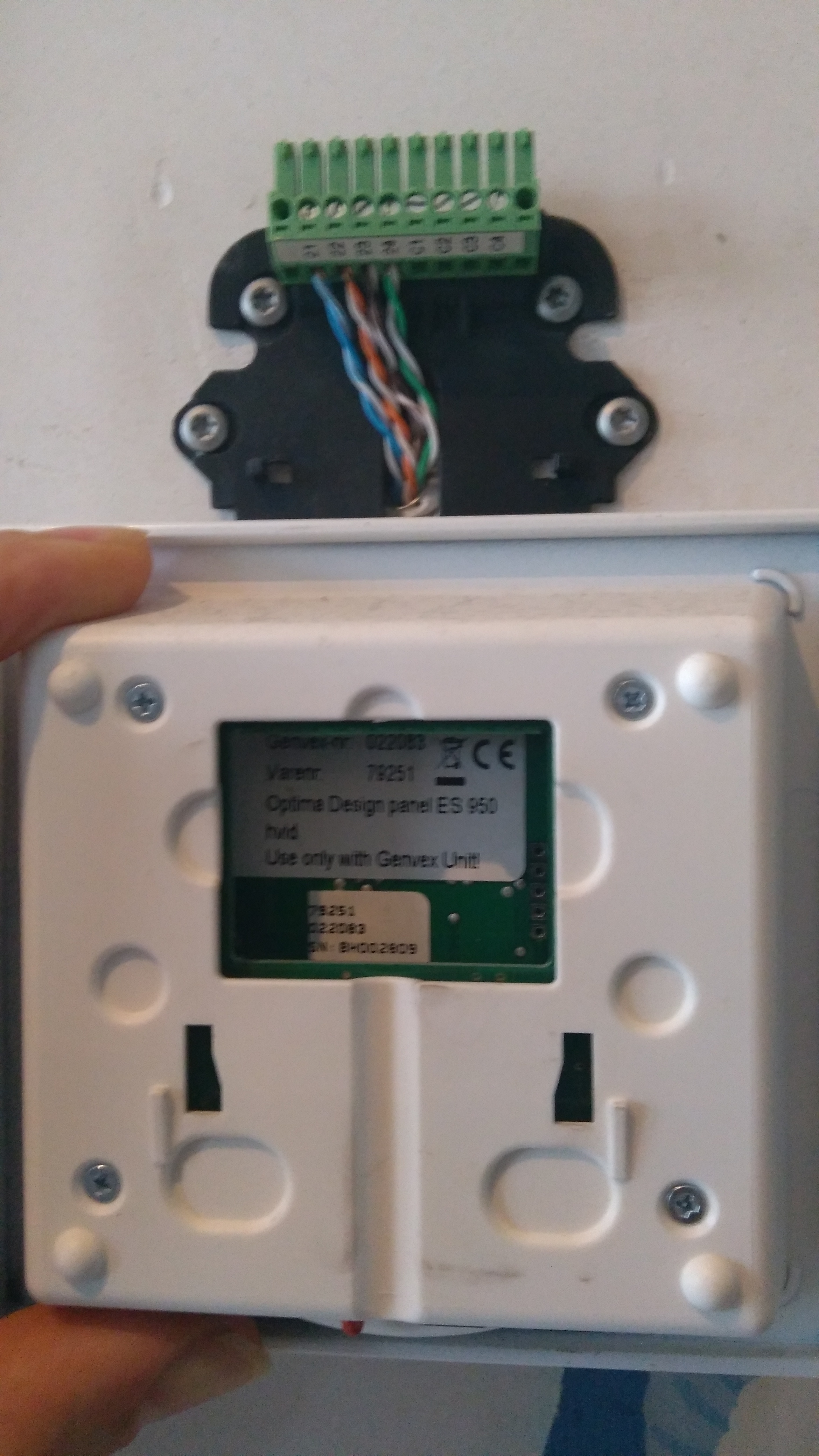
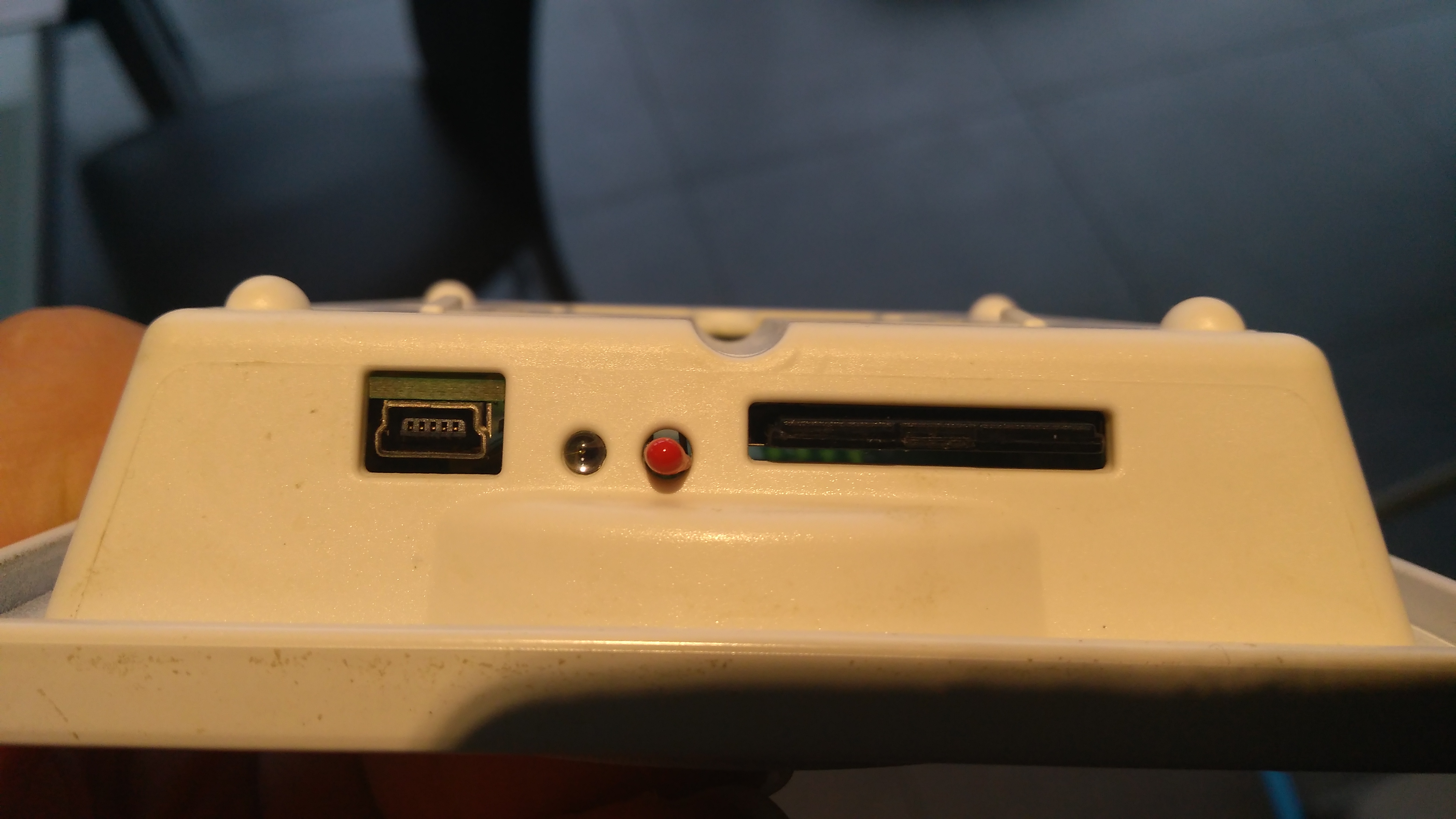
But maybe somebody has some tips? In an Optima-menu I found ‘41 Modbus mode 0 mode’ en ‘42 Modbus adress 1 adr’. The Optima has an usb-interface, a sd-card and the back of the panel says:
Whilst this manual is not specific to the Combi 185 / Optima 311, it’s highly likely the company use the same set of data points for a whole range of products. Comms looks possible on RS485 @ 9600 Baud. http://www.n-compass.io/download/documents/Modbus_Communication_OPT250_V3.1_20.11.14_en.pdf
Of course, experiment at your own risk! If in doubt, just sit and read values, record and plot them perhaps. Get used to how the machine currently operates, what “looks normal”.
Have you looked what files, if any, are on the SD card?
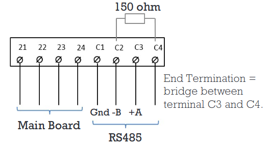
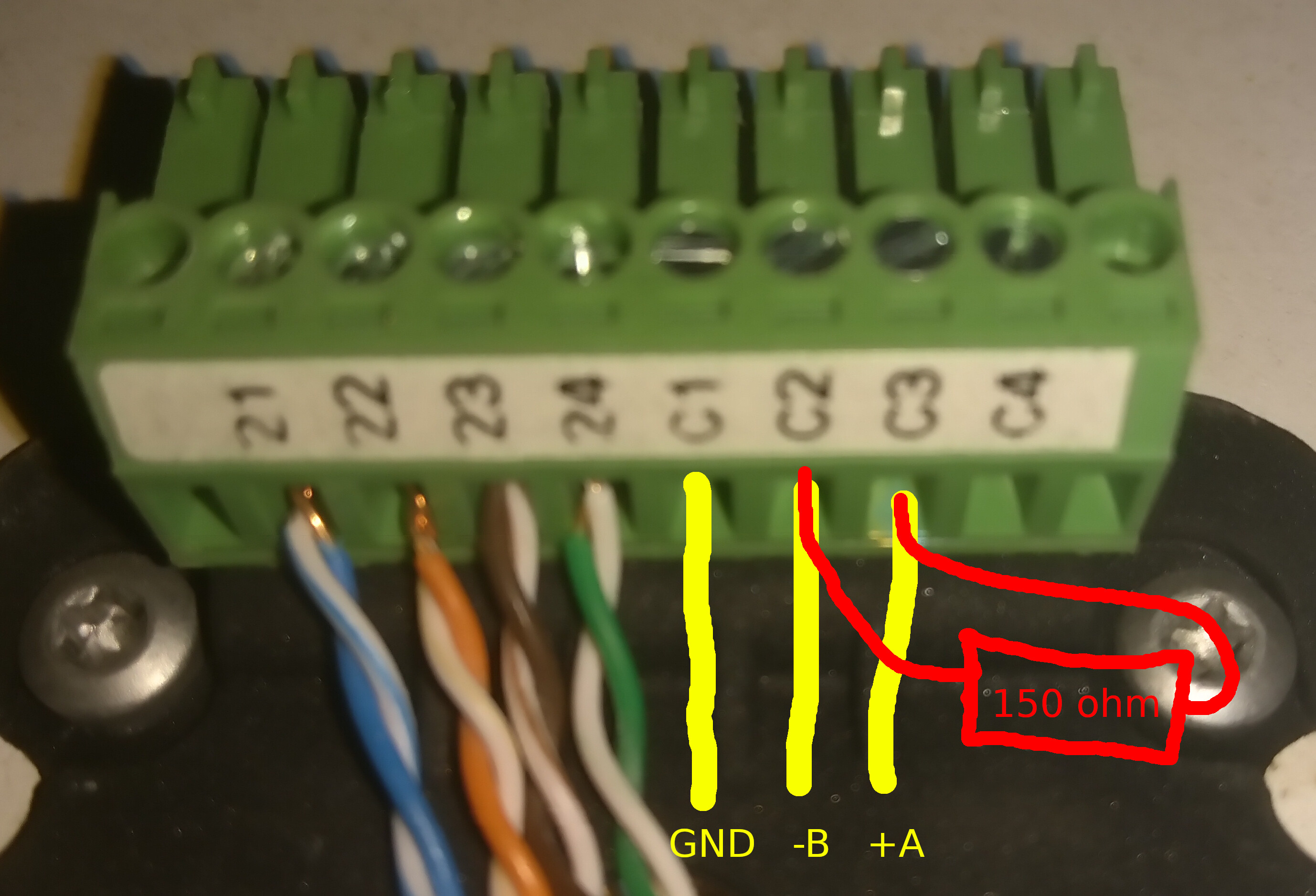
That document and info looks promising. Thanks a lot! I’ve search for info, but I couldn’t find how to read values. I guess I have to use twisted pair to connect to C1-C4 (see screenshot), but what about the other end? Or could I use the USB-outlet to connect to a computer? What ‘Modbus master application’ could I use? Sorry for all those questions.
The sd-card has folders DL01 to DL06. In those folders there are lots of files DL0000.DAL, etc… They appear to be csv-files:
001232;001248;001142;001157;001149;001157;003001;002220;001119;000055;000057;000000;000000;000000;000000;000000;
001232;001248;001142;001157;001149;001157;003001;002220;001120;000055;000057;000000;000000;000000;000000;000000;
001233;001248;001142;001157;001149;001157;003001;002220;001119;000055;000057;000000;000000;000000;000000;000000;
It also has folders SET1208, SET1210, SET1211, SET1301, SET1302, … Within there are S240812.SET, S260812.SET, … They all seem to have as contents:
01 Temperature       18.0\00 \B0C
02 Domestic water    48.0\00 \B0C
03 Heat. elem.       OFF   OnOff
04 Level 3-4 hrs     OFF   OnOff
05 Filter change     4\00     mon
varvar                     var
10 Level 1 supply    30\00   %
11 Level 2 supply    55\00   %
etc...
In the rootfolder are 185 files that include a language code (CZ, DK, FR, …). Doesn’t seem that important. Finally a ES950.hex, ES950.ZZZ and SDTEST.TST. Only the first seems important:
Whilst I have not tried this yet, I have read of others on here using a USB to RS485 dongle on other equipment, connecting +A -B & GND wires to the dongle. I think you’ll also need the 120ohm termination resistor in play as the heat pump control looks like it will be at one end of the network and your USB-RS485 dongle at the other end, again with a 120ohm termination resistor in play.
You would then need to have some sort of script running that sends Modbus queries and forwards the responses onto EmonCMS for processing. Search this forum for “RS485” and have a look at what others have done so far for similar tasks.
The SD card contents are interesting. I wouldn’t be surprised if the CSV file is a data log output of some sort. The SET files look like settings stored? Does the 02 Domestic water value of 48 reflect your current DHW set point on screen? If so it looks like current settings are perhaps stored on the SD rather than NVRAM on the board.
You may not need the termination resistors. For short runs, (less than a few metres) the absence of
terminators usually has no ill effects. It definitely won’t hurt to have them in any case, i.e. a long
or short cable run. One caveat though. Sometimes the instrument will have a terminator built in, thus eliminating the need for the user to add one. If the instrument has a built-in terminator
and an external one is connected, the result is likely to be no (or intermittant) operation.
The drawing shown above is incorrect.
The terminator resistors should be connected across the A and B terminals.
Depending on the OS you’re using, an app may be available to ease the process of querying the
instrument. More info on what’s available here: Modbus Technical Resources
In addition to a way to read the instrument’s registers, you’ll need the register map of your instrument.
The manufacturer’s website would be the first place to search. (or perhaps Google)
Setting up and using Modbus is not difficult, but neither is it trivial.
You may want to avail yourself of a Modbus tutorial. There are many on the 'net.
YouTube has several that range from overview to in-depth.
About the hardware: I’ll have to look for such an USB to RS485 dongle. I’m not sure how to connect is. Is the picture correct? With the resistor that might not be needed. I’m not sure about the value: the documentation says 150 Ohm, but moojuiceuk talks about 120 ohm. I guess it doesn’t matter thát much.
I have Windows, Linux and Arduino Uno at home. For my first steps I guess a graphical program might be the most easy. I’ve looked at Modbus Technical Resources, but the list is long and I’m very doubtful about what to choose. I have used WireShark before, but I’m not sure if that is a good choice. As for Modbus, I found this video a good intro to know a bit what it is all about. I guess my quest isn’t over yet…
Later on it might be the most easy to have a Raspberry Pi or Uno to do something with the Modbus queries. But for the moment I already would be very happy if I could read the values on a Windows/Linux computer and change a setting. Eg. change the setting fordomestic water from 48 to 55 °C.
About the SD Card
I also think the “001232;001248;001142;001157;…” refer to some sort of logs. There seem to be 4 such DAL-files each day. I already tried to figure out what they meant. My best guess would be date, time and temperatures (there are 9 sensors), but I can’t seem to map them to correct temperatures. The values 000055;000057 refer to “55% supply;57% Extraction” that looks obvious if I compare this with what the Optima-display says.
The SET-files. Indeed, the 02 Domestic water value reflect the current setting. If they are stored on the SD rahter than NVRAM on the board, then I might have a problem if I (ever) succeed in building my own application? Eg. my future application notices that there is lots of power from PV and says to the heat pump that domestic water can heat up to 65 °C. The Optima might change this again to 48 °C :-(.
They’re avaialble from several sources, flea-bay and Amazon among them.
I’ve used this one with good results:
Low cost and gets the job done.
Typically, an RS-485 terminator value is 120 Ohms, but since your instrument’s docs say 150,
I’d be inclined to go with that. That said, a 120 Ohm terminator may indeed work just fine.
Thank you for the two suggestions! Your RS485 converter has 2 connections. That will be for C2 (-B) and C3 (+A). But what about C1 (GND)? And I guess C4 just isn’t used? Although 21, 22, 23 and 24 are all used to connect the Optima display with the Genvex heatpump.
Yes, but there are some manufacturers that get the A,B and/or the +/- reversed and that applies to both ends, it won’t cause any damage if these 2 data wires are reversed, it simply won’t work until you swap them round, something to bear in mind if it doesn’t work first try.
Debatably optional, the rf485 spec doesn’t need the gound connected as it works on voltage difference across A,B. But sometimes it is recommended, in the case of the adapter with just 2 comms and no find, the decision is sort of made for you, but should you need a hand one could be added between C1 and the divide the adapter is plugged into.
Looking at your screen shot, there is a nightmare about linking C3 to C4 IF termination needed, this suggests the termination resistor is in-built and perm connected to C2, IF needed you can bring the resister into play by linking directly on the terms so no other wiring need be attached to C4 by the looks of it.
In most cases you can just hook up the A,B wires and your good to go when it’s a short cable run and or a single slave device. But don’t be disheartened if it doesn’t work first time as a little bit of trial and error with polarity, gnd and maybe the resistor link will usually sort it out without to much fuss or risk.
A common misconception is that RS-485 is a two-wire network, but it isn’t. Here’s the lowdown:
The confusion arises because the term “ground/earth” doesn’t clearly convey the idea all of
the devices in the “chain” need to be bonded together. Whether or not that bonded connection
is earthed, is a separate matter.
I prefer “common” in a situation like that. A ground can be, but might not be, a common (equipotential) connection. If the “earth” connection happens to carry a significant current, possibly a fault current, there might be a significant voltage between points that ought to be at the same potential.
The last posts are very informative, but a bit technical for my dummy knowledge. If I would need a common(COM)/ground(GND), then it’s not clear for me what “one could be added between C1 and the divide the adapter is plugged into.” exactly means.
I’m afraid Paul’s typing went a bit awry there.
What I think he means is you connect the C1 terminal to a GND terminal (if you can find one) on the equipment on the other end of the RS485 - that’s your USB dongle. If that hasn’t got one, find one on the other end of the USB cable - presumably your Raspberry Pi.
While searching, I have seen USB-RS485 dongles with A-B-GND(RS485)-GND(out)-5V(out) or A-B-GND-5V(out) or A-B (like the suggestion of Bill) or A-B-GND.
I will probably start with using a laptop with Windows 10, this Modbus Master Simulator and the USB-RS485-dongle that Bill suggests. Than I will not have a GND terminal at hand. But it’s worth trying without. If I would build something (in the future) with a Raspberry Pi, I can use a GND terminal from the board.
Indeed it did, I meant “one could be added between C1 and the device the adapter is plugged into.”
There is indeed a lot of debate around this subject and I have seen many good articles on both sides of the argument. I’m of the opinion that rs485 IS a 2 wire network as it is called such in the official rs485 specs, but I also understand the reasoning for bonding in some circumstances and that many would argue ALL circumstances. But since I have worked with devices that have no 3rd (gnd) connection, such as the rs485 usb adapter linked earlier for example, and have not experienced a device that wouldn’t work without a gnd, I am not convince they are mandatory enough to make it a 3wire network. I have also worked with optically isolating rs485 usb adapters and bonding those would have no effect as the A and B are isolated and have no ref to gnd/common.
I have also had a glimpsing experience with a MVHR unit that had rs485 terms for connection of the remote control panel and when talking to the manufacturers (or I think importers/distributers to be accurate) technical team about the possibility of not using the supplied panel and using a BMS connected to the rs485 terms, the advice given was “yes that can be done, but be very careful as the rs485 is at 240v” which came as a surprise. As I was only advising the installer on this occasion, I recommended (with many caveats) NOT connecting the common to avoid delivering 240v to the BMS and use a optical isolated rs485 adapter, to my knowledge that install is still in service.
I’m sure this long standing debate will not be settled here and now, but I am happy to be aware of both arguments and accept that I’m not knowledgeable enough to write off either position.
As I see it, the problem is simple. The solution: not so.
It all depends on the range of common-mode voltage that the RS 485 input can accept.
If the difference between the two “ground” or “earth” (call it what you will) voltages is less than that, there isn’t a problem. If it is greater, then the input is likely to be damaged.
If the source of the voltage is pickup and leakage, connecting the two grounds/earths is the solution. If however it is like MVHR unit you mentioned, the only solution is an optically (or otherwise) isolated adapter.
I’ve been doing similar things with a Grant ASHP. There is a set of RS485 terminals on the main unit PCB, but there was no output whatsoever (checked on a 'scope). In the end, I opened up the (wired) remote, found a UART, and just read that. Reverse Engineering Grant ASHP Remote Protocol | Hackaday.io This is monitoring only, but I’m sure it would have been possible to replace the remote entirely and adjust settings if I’d been stubborn enough!
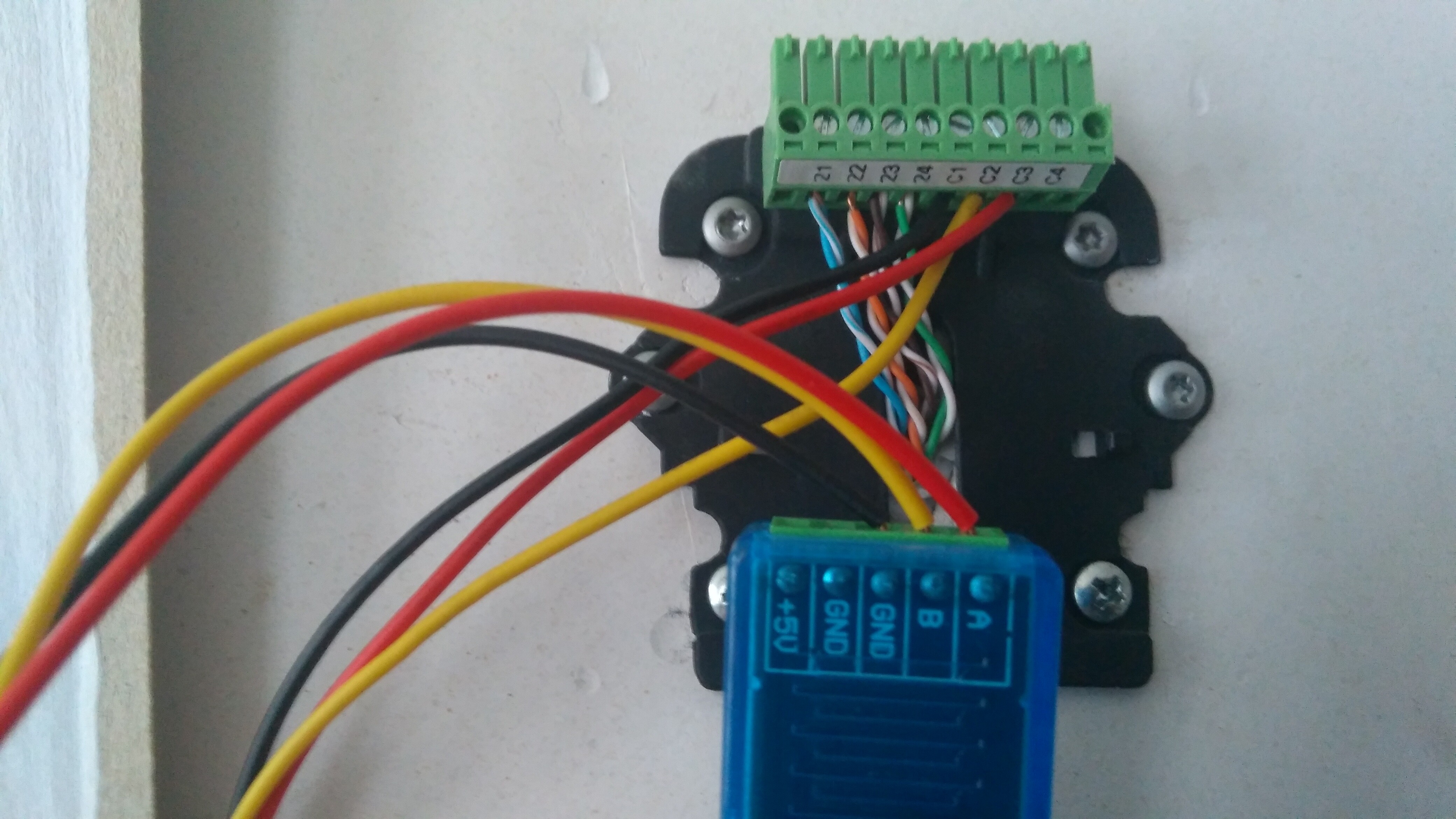
I finally took some time to try… but I failed. What I did:
I’ve connect a USB-RS485 connector and installed the driver. I had a look at the device manager and saw “USB-SERIAL CH340 (COM3)”.
I did the (ca. 30 cm) wiring: see photo. Then I reconnected the Optima display. I guess this I necessary, but I’m not sure.
I downloaded the Modbus Master Simulator (thx Bill.Thomson). And I did the settings in Connection > Settings (thx moojuiceuk for that pdf-document).
Protocol: Modbus RTU
Port: COM3
Bitrate: 9600
Parity: EVEN
Stop bits: 1
I don’t understand ‘Addressing convention’, DTR, RTS or General. So I used the defaults.
I made a connection from the dongle to a Windows laptop. Just to work easier I used a female-male USB cable of 1 meter. I got a red ‘Modbus message timeout’ in Modbus Master Simulator. I see as many polls as there are errors in the status bar :-(.
I swapped A and B wiring at the USB end, but I got the ‘Modbus message timeout’ again :-(.
Some questions I still have:
I guess I can try to connect a 150 ohm resistor from A to B (see my picture posted on Nov 2020)? Could be that 120 ohm works as well. And retry a reading. After that, I can swap the A and B-wiring again and retry?
@Bill.Thomson, you were talking about “In addition to a way to read the instrument’s registers, you’ll need the register map of your instrument. The manufacturer’s website would be the first place to search. (or perhaps Google)”. But I guess that I don’t need it yet, because I’m just testing the connection at the moment?
You actually do need it now.
The modbus simulator is expecting a reply and unless you query the device with a valid register
number, it might respond with garbage, or not respond at all. There’s no risk of damaging anything,
just that your device may not respond to an invalid register inquiry, hence the timeouts you’re seeing.
Although the spec calls for even parity, from what I’ve read and seen, no parity is used, so give
that a try as well.
For short cable runs, it’s quite common to not need the 120Ω terminator resistors.
 .
.