I have 5kW Ecodan R290 FTC7 with a pre-plumbed cylinder and I am considering removing the pre-plumbed low loss header (LLH) and heating circuit (Zone 1) pump, to drive everything from the pump in the external unit. This is because I am struggling to increase the ΔT that the heat pump (HP) is seeing from my underfloor heating (UFH) . From my measurements, I am achieving ΔT 7K across the UFH manifold, at a total flow rate of ~6l/min (all flow regulating valve (FRV) flow rates added together), and the lowest I can get the HP pump to go is 9l/min. The LLH is therefore mixing 7K ΔT water at 6l/min with 9 l/min flow from the HP resulting in ΔT 3K (sometimes I temporally get 3.5/4K) going back to the HP.
One limitation I am aware of is that if the flow through the 5kW Ecodan drops below 5l/min it enters a fault condition, so 6l/min is sailing very close to the wind. Does anyone know if the pump in the HP is being controlled to constant pressure or constant volume? If it is constant pressure it will work (as long as I say above the minimum flow rate), if it is constant volume, it wont work. I guess I could achieve the same thing without removing the LLH by adding a regulating valve to the primary circuit to control the flow rate, does anyone know of a suitable regulating valve?
Are there any other options? Are there any other risks? Has anyone ever done this?
EDIT: To clarify, I don’t just want to increase the ΔT for a better CoP (manufacturers quote everything at ΔT 5K) but I need to increase my ΔT because I am not getting enough heat into the house on the coldest days:
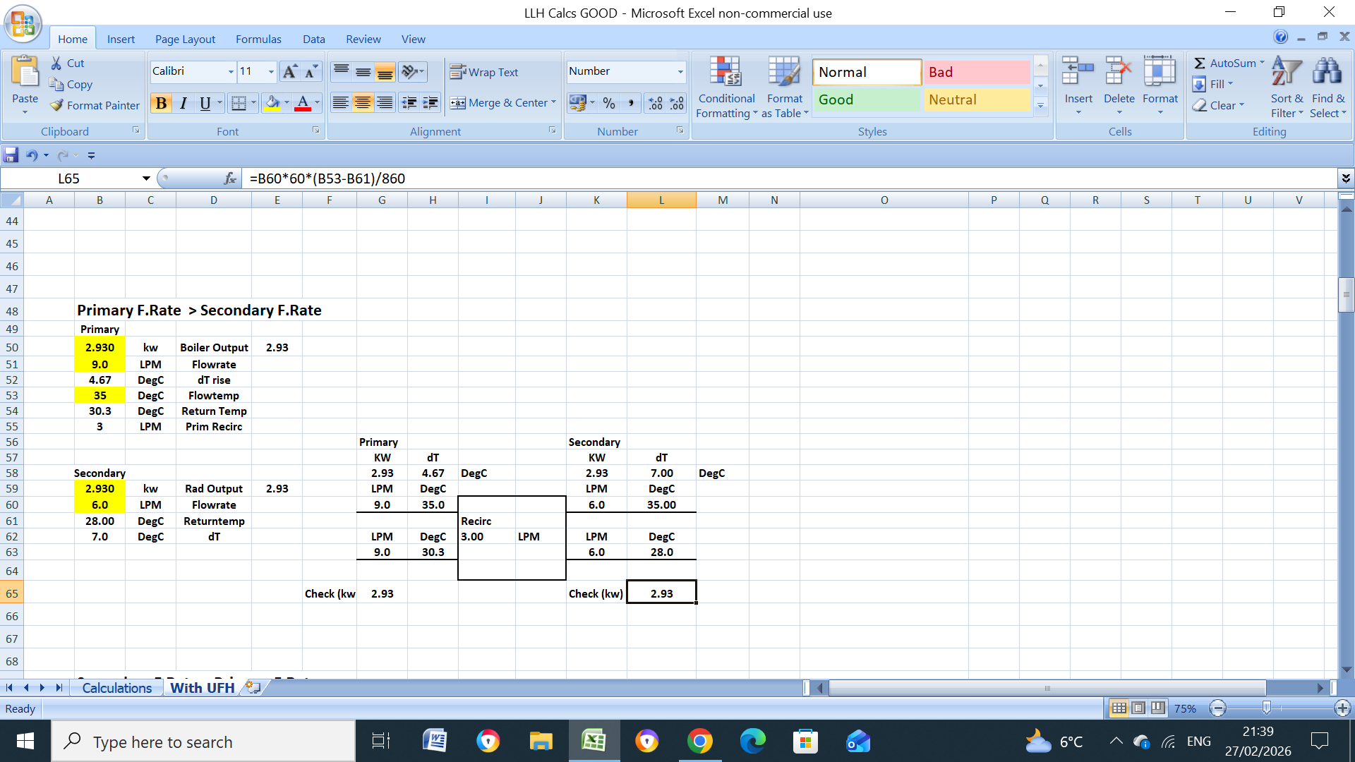
9l/min @ 3k ΔT = 1.88kW
6l/min @ 6K ΔT = 2.51kW
6l/min @ 7k ΔT = 2.93kW
My heat loss at -3.6°C is approx 2.5kW so I need to achieve at least 6K ΔT
EDIT 2: I can also achieve 2.5kW with 9 l/min @ 4k ΔT, but I cant seem to be able to consistently achieve that ΔT, no matter how hard I try, I can only temporarily achieve 4k ΔT.
What is the HP, LT, (leaving temperature), if you increase this it will increase the UFH output, my calcs show the primary side dT is almost 4.7C based on your data, I’m only assuming a LLH primary temperature of 35C.
Your right, my measurement of dT on the UFH or primary must be wrong, because if I was getting dT 7 @ 6 l/min there wouldn’t be a problem. There may also be some variation on the UFH flow rate as I am visually setting the FRVs (in addition to any variation from the valve itself). I only have the thermocouples on the primary that come installed on the pre-plumbed cylinder, on the UFH side I have been making best efforts with an IR thermometer but there is a lot of variation in my measurements, therefore my UFH ΔT must be lower than 7K.
I would be delighted if my system was doing what you have modelled, unfortunately, it is not. The only thing I know is at a flow temperature of 40°C I can get a ΔT of 3K, if I try to go lower into the high 30s the ΔT plummets and the heat pump is unable to modulate low enough so it overshoots the set-point and the heat pump cycles. Ultimately the issue is that this heat pump is oversized, so I am just trying to make the best of what I have got.
I can just keep running a higher weather compensation curve than I should need (to keep the ΔT high enough to deliver the required heat) but I would like to enable lowering the weather compensation curve, however low ΔT is preventing me from doing that and even at the design point for my system (45°C at -3.6°C) the ΔT is not high enough to deliver the required heat.
Can you increase the UFH flowrate(s)?, the closer the (LLH) primary and secondary flowrates get the better, if both exactly the same then obviously the effect is the same as having no LLH, if the UFH flowmeters are fully open can you increase the pump speed?, assume there is no TMV on the UFH manifold?.
Does the HP heat a HW cylinder by using a 3 way diverter valve, if so, the valve might be leaking (bypassing) HW and mixing with the primary return when no cylinder heating required.
Yes there is a 3-way valve, I guess it is possible there is some leakage, I could measure the temperature of the hot water pipe down stream of the valve, short of putting a flow meter on it.
If I could achieve the below I would be happy, but it has eluded my thus far:
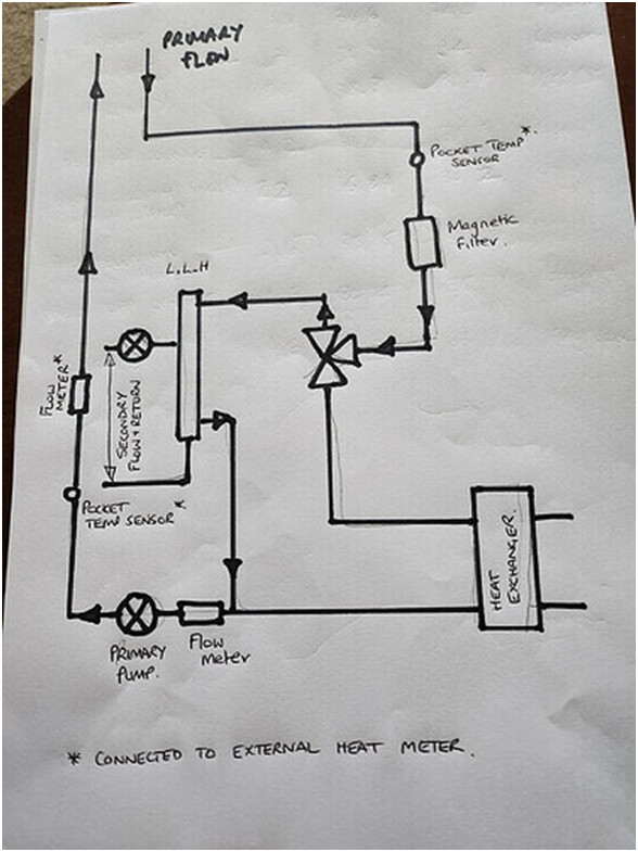
You should get a very good idea by just feeling it, here is a schematic (not mine), which uses a Diverter Valve/PHEX (Mitsu Zubadan Flow Temperature Issues), problem solved with a new replacement Diverter valve.