Recommendations for running a Samsung 6th Gen with Octopus

Afternoon again, Sarah.

Thanks for your very informative answer.

I did wonder whether there may be a 3-way valve set-up somewhere, so I’ll need to take a closer look. As there are only 2 pipes to the HP, I’m sure that they’re simply flow & return, meaning that any split flow control must be situated outside the Samsung system & therefore could be subject to the design whims of my dissapointlingly ammateur installer. Also our heated towel rails run off a completely separate controller, so the same goes for that circuit.[Edit] Can’t get to see it all too easily, but it looks very much like your 2 X 2-way valve suggestion, which concurs with your thoughts on non-simultaneous ops - which will save me some bother.

The towel rail cct is a separate item altogether - with its own valve controlled by a separate controller on the wall. Overkill, methinks, but I do want to try and bring its control into HA, and the controller (just like my installer) is not smart. However, in true Baldrick fashion, I’ve hatched a cunning plan to try and bring the control in, via a spare circuit in the Heatmiser UFH wiring centre (in the same cupboard) - which I’m hoping I can control via the existing HA/Heatmiser interface I already successfully utilise.

Thanks for the thoughts on F1/F2 & F3/F4. I’ll need to bottom this out.

The disinfectant cycle for the DHW is programmed via FSVs, so your comment about those piqued my interest, thanks; maybe I can access them via F1/F2.

I’ve been operating this pump from new - for about 2 years, so I’m fairly au fait with Water Law not affecting DHW, thanks.

This is the second winter that we’ve had the HP heating the house…

…nowadays, I just use the room stats as wireless switches - in case I do wish to isolate a particular room (rarely the case) - but generally, I have them all set above the level at which they may trigger their respective loops to shut down i.e. 25° C. This way the HP runs 24/7 as do all of the loops in every room. The Water Law keeps the outlet temp sufficient to maintain our main areas (particularly the kitchen) at circa 20° C, and the other areas at 16 - 19° C. Continuous circulation keeps the slabs warm 24/7, so both tiled AND carpeted areas are nice and comfy to walk on, barefoot.

Lots of info here, but I’m sure someone else will , eventually, find some good titbits.

Thanks for the comprehensive reply, @Sykes.

I wonder if you are misinterpreting my terminology here. When I use the term “roomstat” I am referring to the wall thermostat that, (if you have one) switches the whole space heating system on and off, as opposed to the TRVs you may have on individual emitters? These are indeed thermostats, but not roomstats. Not every installation has a roomstat (which may or may not incorporate a programmer) - some set-ups just control room temperature on the timer, or even a hand switch.

Good luck with the cunning plan for the towel rail, let us know how you get on…

Thanks for the reply @SarahH

I have 6 wireless room stats in total (no TRVs, as we don’t have radiators any more).

Some control the individual UFH loops in just one room (the rather large kitchen, for example) and some control loops in multiple areas - one hallway stat for example, controls the hallway UFH loops, two bathroom loops, along with another shower room UFH (only one loop). The [Heatmiser] room stats (wireless thermostats) wirelessly pair to two Heatmiser ‘Wiring Centres’ which are mounted immediately above their respective UFH manifolds. Each stat sends on/off control signals to its respective wiring centre, which in-turn drives the respective loops’ valves either on or off.

I also have a Heatmiser ‘NeoHub’ which also connects to the wiring centres, and allows connection to the house network, via LAN. As with most systems, Heatmiser provide cloud connection to their servers, which in-turn allows in-app control to one’s own system, when on safari. Good-’ol Home Assistant also allows a super level of remote control, thanks to a couple of ‘Heatmiser’ integrations provided by some top Folk, happy to publish their work for the good of others, rather than for personal gain. Thanks to all such Folk (also found on this site), for which I thank each and every one.

I will do, although it looks like I’ve got some more legwork to put in, before I get to that little problem. Hopefully @toadhall might oblige…

Thanks again.

Baldrick.

1 Like

AFAIK you can’t update time schedules from Modbus, however ………

  • You can turn the indoor unit On/Off via Modbus (register 52, 0 = Off, 1 = On). You can then implement a more sophisticated scheduler in HA and just not use the Samsung inbuilt scheduler. You would need to add the HA Modbus integration to HA, then HA should be able to control the scheduling.
  • Also, if you disable the Samsung inbuilt weather compensation, then you can set the Water Flow Temperature via Modbus (register 68, value in 1/10 degC). You can then implement a more sophisticated weather compensation in HA, possibly adding in load compensation as well.
  • I only use the heat pump for heating, not DHW. Looking at the MIM-B19N installation manual then register 72, 0 = DHW Off, 1 = DHW On should toggle between heating and DHW and register 74 should set the DHW temperature. It goes up to 70 degC, so I assume it switches in the immersion to reach the highest temperature.

So mostly it should be OK. Maybe the fly in the ointment is the RS485→USB→Access Point. The RS485 will be speaking Modbus RTU and the Access Point Modbus TCP, so you might have to rethink that. I don’t use the HA Modbus Integration nor DHW, so I can’t comment on their robustness, but straight Modbus control works fine.

Good afternoon Alun @toadhall

Thanks for the reply. I’ll need to re-read your thoughts several times before moving forward. It’s clearly more complicated than I’d hoped, though. I really thought it would be straight forward to do something as simple as setting timers on the blessed thing. From experience, the more complicated you make something, generally the more ways it can find of tripping you up. I hoped to be able to just bolt this module in, and get a connection back to HA, where I could do a bit of wizzardry, and come up with a quick, easy solution.

Please may I ask to what you’re referring when you say ‘Indoor unit?’ As you suggest, all I want to achieve is timed control of the heat pump’s DHW cycle, (along with access to the disinfection cycle) so as long as I can switch these on & off with HA, it’s just a matter of creating some simple Date Time Helpers within HA, and job’s a good ‘un.

If I can get over the first hurdle, I can then look at disabling the Water Law, too.

Because I run the heat pump 24/7 during the cold months, this may be all I need. If I understand correctly from @SarahH , switching to DHW should cause the HP to temporarily stop space heating mode; if this is the case, then this is all I need to do (using HA timers for ‘programme control.’). Despite you not utilising this, would you expect me to be able to set these registers (72 & 74) via the route you currently use - i.e. F1/F2 connection?

Thanks again.

It is either attached to your DHW tank if it was a Samsung pre-plumbed tank or is a separate beige coloured box with a big Samsung logo on it.

Yes, although I don’t use them they are just different registers on Modbus. They will normally be driven by the Samsung DHW schedule, so you have to remove any time schedule entries, otherwise it will overwrite what you send from Modbus.

If you can, I would run the Modbus twisted pair back to RS485→USB converter plugged in to your USFFC and avoid the Wi-Fi connection (just more stuff to go wrong). Modbus will work over long distances (1km), so the few tens of metres found in a domestic installation are no problem.

For removal of doubt, @Sykes, the “Indoor Unit” (aka Tank Integrated Hydro Unit) looks like this:

The MIM PCB can be seen about half way up. Judging by your earlier photo, you have the standalone version, not the integrated version.

Ah haaa! @SarahH @toadhall thanks both. I now understand that I have a non-Samsung set up, in so far as my DHW tank is from a different stable - with the MIM-E03 (‘Indoor unit’) separate to the cylinder, and separate to the Wired remote controller, whereas the ‘Standard’ Samsung design has the MIM-E03 attached to the side of the tank, AND (in some cases) has the wired remote controller bolted to the MIM-E03**.

@toadhall Thanks for the previous reply; all noted, and more meat on the bone…

Folks

For anyone contemplating the same journey as me, I thought I’d report back as to progress…

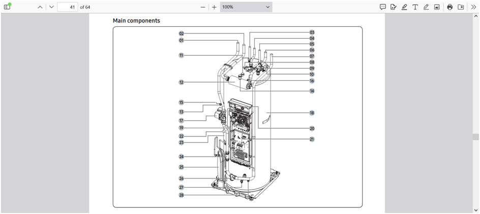
I eventually mounted the MIM-B19-n inside my heat pump, where there was a white plastic ‘slot’ into which it directly fitted (no need for the supplied black holder) taking the power from R1/R2 on the main board - with the supplied cable, and comms also with the supplied cable - back to the snap-in connector on the main board. one of the cables only just reached.

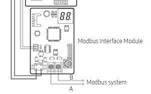
You need to decide what ‘address’ you set on the MIM-B19; you do this with some tiny dip switches, and a rotary selector - both on the board itself. This address is used in your subsequent code (YAML within Home Assistant, in my case) to dictate from and to where the MODBUS messages are transmitted. I think the factory default was either 0 or 1 on the rotary, and all dip switches set to ‘off.’ I plumped for ‘4’ which I set on the rotary dial - particularly as I didn’t want to mess around with the dip switches. Just remember that you need to know the address which has been set, as you’ll need it later on, and you don’t want to be taking the heat pump apart unnecessarily. You also want to set this address before installing the board, as it’s fiddly enough with the MIM-B19 accessible, let alone installed. An example of the modbus wiring guide is here.Note the requirement to ground the comms cable at one end only.

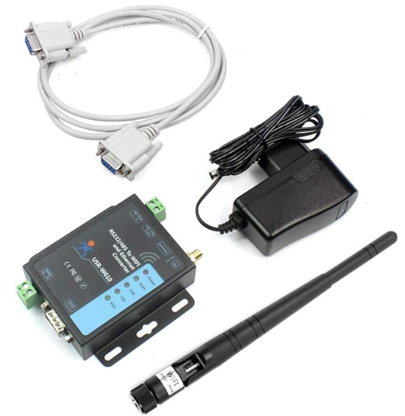
I was determined to use a wireless solution, eventually opting for one of these W610 boxes, which not only acts as the wireless bridge to your network, but also translates the modbus / RS485 into something which can be transmitted over TCP - and therefore, your network, and on to Home Assistant:

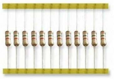
The other 2 things you need to get are a length of cable - to run from your MIM-B19 in the HP, to wherever you decide to locate this ‘converter,’ and a couple of 120 Ohm resistors. I didn’t want to be messing about with electronic components to begin with, but to be honest they’re easy to come by, and cheap-as-chips (as we say in England.) They’re also easy to fit. They effectively help to reduce noise generated in the cable, which can ruin the modbus messages, so it’s quite important to do all you can to suppress unwanted garbage from giving you an issue. I have read that the resistors aren’t necessary for short cable lengths, but as I was running my cable through about 2m of ducting which also carries the mains for the HP (which can draw upward of 7-8 kW when doing a DHW cycle) I decided to put a resistor at each end.

I got a strip of 100 for £3.79 at Amazon here, so I’ve got a few going spare…!

The cable needs to be shielded, and a ‘twisted pair’ to also help reduce interference. Most local places don’t seem to stock this ‘niche’ stuff, so expect to have to order it. I used this one, which seemed to be good value at 48p /m. Think carefully about siting your W610 - you don’t want to be suffering from poor Wifi signal - and only then decide on cable length.It also needs to be close to a 3-pin UK mains socket.

I did what I thought would be the easy bit first - firing up the W610, then logging-on to it’s own wifi network (SSID ‘USR-W610-xxxx’ where xxxx is the last 4 digits of the unit’s MAC address published on the label underneath the unit). Once in, navigate to IP address 10.10.100.254 with a web browser, which will bring up the unit’s web interface. Log in using the highly secure ‘admin’ for both username & password. I won’t go through all of the settings, but in ‘Quick Configure’ 1F set STA mode, then do a search for your wifi SSID, and enter the password - to enable the unit to connect to your network. You’ll need to continue to change config settings once it’s on your network, so be sure to know what IP address your router gives it; I used the ‘STA Interface Setting’ section, and used the ‘WAN Connection Type’ area to set a static IP address - which was outside the DHCP range of my router - in order to avoid IP conflicts, and to always know which IP address to use in order to log back in and make changes. In the ‘ Wifi-Uart Setting’ page set baudrate to 9600, databits 8, parity even, ‘stop’ [bits] 1, ‘flow control’ and ‘baudrate adaptive’ negative, and RS485 mode ‘enable.’ Further down the same page, note (or set your own) port number as you’ll need this to configure the MODBUS in HA. I think mine defaulted to 8899, but 502 seems to be standard. Remember to ‘Apply’ any changes using the button at the bottom of each page, then restart the module from the ‘Device management’ section when all the changes have been made. User manual (V2.0) is here.

MODBUS is built-in to HA, but won’t be accessible until you’ve actually made reference to it using some YAML (I think). The main thing is - don’t go searching for it as an integration - you already have it.

The comms cable you buy, connects between the two terminals on the MIM-B19, and the W-610.

The MIM-B19 left-hand one connects to the W-610 ‘A’ terminal…

The MIM-B19 manual can be found here.

Once it’s all connected & powered-up, you should be able to use some yaml to make a start on working with it:

I’m not putting everything here, as it’s just a guide, but as a starter-for-ten (good ol’ Bamber!!) I’ve got this in my ‘Configurations.yaml’ folder…

modbus:

* name: w610

  type: tcp

  host: 192.168.1.3

  port: 8899

  timeout: 5          # allow up to 5 seconds for a reply

  retries: 5

  sensors:

  * name: samsung_DHW_temperature

    slave: 4

    address: 75

    input_type: holding

    data_type: int16

    scan_interval: 30


This successfully gave me the state of ‘samsung_DHW_temperature’ sensor, which can be checked in ‘States’ under ‘Developer Tools.’ It’s increased by a factor of 10, so a State of 470, is an actual temp of 47 C.Note ‘Slave’ is ‘4’ - my chosen address set on the MIM-B19 address selectors, before installing in the HP. Also ‘host: 192.168.1.3’ (in this example) is the IP address allocated to your W-610, or the static IP if you select one.

Once you have proof of concept, you can play with it to your heart’s content; there seems to be quite a variation in register numbers & addresses etc, so you can expect quite a bit of legwork, going forward, but there’s a lot of help from some top people out there, so pretty much anything’s possible.

At least, for those folk who want to do something like this, but don’t know where to start, you at least have access to one wifi set-up which has been proven to work.

I now have access to many of the available registers, and crucially, I can now confidentally control DHW cycles from Date/time helpers in HA, rather than having to use the pesky Samsung remote controller schedules to do so.

I hope this helps at least a few Folk starting their journey.

Let me know if it’s been helpful.

Good luck!@SarahH @toadhall

2 Likes

Excellent write-up @Sykes, and quite an achievement :slightly_smiling_face:!

It’s just a shame that you’ve hidden it in a thread with a name that won’t help me find it again when I really need it…
I’m toying with the idea of creating an “index” thread with cross-references to all the different methods and hardware that are available for monitoring and controlling Samsung heat pumps, along with a summary of the pros and cons of each approach (e.g. low/medium/high assessment for each of cost (and benefit)/electronics skills required/coding skills required/data presentation (tabular/graphical)/data export capability/HEMS compliance (e.g. HA connectivity)/MID compliance/etc.) so folk can assess which approach best suits their needs, and points them to posts describing installation details (like yours above).
But probably no one person could write it all - it would have to be a collaborative effort :face_with_diagonal_mouth:

BTW those MIM-B19Ns cost almost £150. Did you justify the cost on the basis of economic payback, or just technical satisfaction?

Hi @SarahH . I did wonder whether I’d inadvertently hijacked the topic, but at the same time, it seemed pertinent to continue with a thread that contained my journey so far. Shall I start a new topic, and copy it into there, or leave things as they are?

On a different point, I tried using code tags around my YAML, and although it seemingly worked by using the ``` symbols, the drop-down for code selection didn’t contain a YAML entry, and despite trying a couple of the others, it never formatted the text.

Yes - currently £175.56 + delivery from Midsummer - ouch! I’d read about Folk obtaining them cheaply from overseas, and had a go at the Portugal option €88.00 I seem to recall, but when I pressed them for the carriage, they finally emailed back and said it would be another €73.00! A friend ordered it for me, trade, eventually.

I can’t claim economic payback, so it would have to be ‘technical satisfaction.’ I think these systems are generally designed to be ‘Fire & Forget’ where the user has little input., once the system’s been set-up. However, because I have an ESS, along with quite a bit of PV, and thanks to the wide selection of ToU tariffs nowadays, I regularly wish to change when I run a DHW cycle, and a disinfection one. I really dislike the Samsung remote controller too, so I’m (or was, until yesterday) Mr. Grumpy every time I wanted to make changes.

I also wish to switch off some of our systems to divert power elsewhere - depending upon amount of sunshine, ToU energy cost etc, so there’s a real need to get the control completely under one system, and I find that HA fits the bill very well. I viewed the cost of equipment, as a gift-to-self, because I’ve really enjoyed learning about RS485 & Modbus (a bit), and because I couldn’t find a similar set-up using a WiFi solution, it’s been great fun researching everything, and being able to pass on my findings, to others (I hope).

Don’t do that. Sarah or I can move it if needs be. What we do not want is duplicates. :smiley:

Robert please could you assist @Sykes with his query?

I was just looking at that. He had got too many sets of ``` – two above the code and two below, and I tried
```YAML and ```yaml
but it appears to recognise neither and formats it as plain text (not that I know what YAML format looks like anyway).

Folks

I’m trying to find a register / address / hidden register for the Disinfection cycle - particularly to control the ‘Interval’ (day of the week FSV3042) and ‘Start time’ (FSV3043), I;ve searched through all of @SarahH ‘s and @toadhall ‘s published documentation, and also trawled t’interweb for some time, but I’m coming up with big fat zeros.

Anyone got any ideas?

TIA.

By 'eck, lad, thah’s not looked too careful.
Try
NASA_Interpreter.xlsx (71.7 KB).
Do a Find & Select/Find/Find All on “disinf” and you’ll find the NASA registers (in the left column) for each of FSV3041-6.

By gum, it’s baltic out ’ere — I’m nippin’ t’ shop for a brew an’ a butty before I freeze me nethers off.

1 Like

:sweat_smile:

Thanks @SarahH

I downloaded this yesterday, but couldn’t see anything that I recognised as a register; I’ve not seen ‘NASA registers’ before. Do they need converting, to get them into something I can use with Modbus?

Yep. You need to read the MIM-B19 manual section about “Adding new Modbus registers”. When I came to do this I found that the on-line PDF was missing this section, but the paper copy supplied with the MIM-B19 had it. Having understood this look at

which will translate what you have to do into HA speak.

1 Like

If it helps, I have a long list of protocol messages which contains all the relevant message IDs and acceptable values.