Help me understand how this works. So looking through EmonLib.cpp on github I’m struggling to understand how Real Power is calculated without knowing the phase angle between current and voltage?
Welcome, Rob, to the OEM forum.
Real power has nothing to do with phase angle.
EmonLib multiplies - and you can see this if you look at the code, line 135 - the instantaneous reading of voltage and the instantaneous reading of current, then averages those values to give the average power. “phaseShiftedV” refers to a small phase shift of a few degrees to compensate for phase errors in the c.t. and v.t.
You can read a bit more in the ‘Learn’ section.
Hello and thank you! It’s an awesome project!
I guess where I am mentally stuck is around the instantaneous readings and the final values starting at line 163. I can’t find any formulas that do not require sin or cos of the phase angle.
I’m guessing there is always a phase difference between voltage and current for a whole home meter where there are various types of circuits on the mains. So wouldn’t you have to figure out the PF first as something like cos((time2-time1/16.67ms) * 360) (for 60hz) and then use that to calculate the instantaneous power ?
Ah, I see where you’re coming from now.
Your mains voltage is a sine wave, and the current is a sine wave, like in the text books. Right? Wrong. The voltage is probably fairly close to a sine wave, even though mine here in the UK has a visibly flattish top to it, but if you’ve got an armful of CFL lights and computer power supplies, then the current can be a long way from a sine wave.
Here’s a picture that a well-respected contributor has posted:
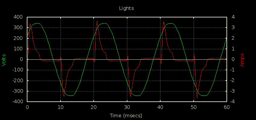
The green trace is voltage, 340 V peak voltage because it’s a 240 V system where he lives. The red is current.
Now I defy you to tell me the phase angle between current and voltage there.
Yet you can easily calculate the instantaneous power: it’s the instantaneous voltage as you sample it multiplied by the instantaneous current also as it’s sampled. Samples were hard to measure with moving coil or moving iron meters, they are very easy with digital techniques. If you take enough samples, and average them, you get a very accurate reading of the average power.
It’s an unfortunate fact that all the text books assume a nice simple sine wave, then they teach P = V.I.cos(φ), whereas in the real world, you don’t always get a nice sine wave - especially with electronic devices as the load.
And when you haven’t got two nice sine waves, P = V.I.cos(φ) is meaningless, because φ itself is meaningless. (It works for the fundamental 60 Hz, and for pairs of harmonics individually - and each pair will have a different φ. Overall there’s no concept of a single phase angle. Some people, who’ve read the theory of pure sine waves in Wikipedia, work backwards from power factor and get an angle, but it has no physical meaning.)
Now while we’re at it, p.f. = cos(φ) is derived from the maths for sine waves, and it only works for sine waves. It’s not the definition of power factor. The actual definition is
power factor = (real power) ÷ (apparent power)
and that works for the sort of load in the picture above, because you can use maths on the voltage samples to get the rms value, likewise the current samples, and then multiply the two rms values to get apparent power.
This is what happens at line 163: A few lines before, from line 156, you had the maths to calculate the rms values: sqrt(sumV / numberOfSamples) (and scale them into the usual units), and as you go into line 163, you have the sum of the instantaneous powers sumP. All that line is doing is taking the average by dividing the sum by the number of samples, and scaling it. And the next 2 lines are getting power factor from its definition.
5 Likes
Damn that made perfect sense, big thanks for the visual now I get it. I wish there were more real world explanations like at the top of google searches!!
Thanks so much, this was driving me crazy!!
3 Likes