I’ve installed my emonpi today configured for solar. I installed it at dusk and was impressed that my solar panels were still generating. They’re apparently still generating now making 16W. I was perplexed so I turned off the fuse in the fusebox for the PV. The Generation meter switched off indicating the circuit was broken (as expected). Unexpectedly, openenergymon now records that solar is generating 24W!
I powered down the emonpi. I swapped the CT Sensors over. I rebooted the emonpi. With the solar still switched off, the swapped CT Sensor read 24W again. Turning on the circuit again, it again reads 16W.
It is most likely noise and pickup, possibly within the emonPi itself, possibly from adjacent circuits.
It’s quite hard to measure zero - that implies absolutely perfect analogue electronics, which unfortunately we don’t have - so the usual ‘cure’ is to add a step in the processing to ignore the output (set it to zero) when it’s less than a few watts. In your case, I’d wait until you’ve seen a day or two’s generation, and then choose a number that’s only just above the ‘nighttime’ value you see.
There are two ways you can tackle this:
If it looks as if the 25 is reasonably constant, you can subtract 25 always. If it isn’t, then you can subtract a smaller number, and then zero the value if it’s below your new threshold.
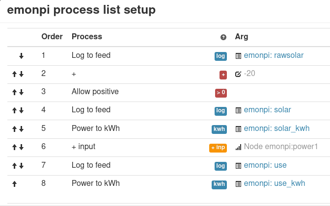
In emonCMS, on the Inputs page, look down the processes. For the first option, you want to add (+) -25.
For the second option, further down you’ll find “if >, skip next” and you skip if greater than (say) 25, then the next step is of course “Reset to ZERO”. (What you’re actually doing is: if ≤25, set to zero.)
One thing you should check - is the c.t. the right way round? Your generation should be a positive value, and in the dark, most inverters consume a small power, so it should read a negative value at night. That it read higher with the inverter alive suggests something to be checked when it’s working.
Thanks. I’ll re-examine when I know the solar panels are generating.
Just to clarify - it’s reading 24W when the inverter circuit is broken (off at the fusebox) and lower at 16W when the inverter is in circuit.
The CT clamps are both on Brown wires. It’s a type 2 setup. They’ve both got writing on the Fusebox side of the CT clamp. I think that’s right.
I don’t know if it’s related but on startup, the emonpi’s onboard display was a bit flickery, & looking at DMESG’s output, I got 30 under-voltage messages. Is that normal?
That should be consistent. Our convention is the house/grid shows positive at night when you’re definitely consuming, and the PV is positive when generating.
The emonPi display should not flicker, it sounds as if there could be a problem with the mains socket that the 5 V supply is plugged into, or the 5 V supply itself, or the lead, or the emonPi. Without a bit of wiggling and tapping, there’s no way of knowing. If you have a suitable ( > 2 A) 5 V USB supply available, you could try a substitution exercise as well.
The a.c. adapter does not supply any power, it’s only measuring the mains voltage and providing a phase reference to determine the direction of power flow.
If you can’t pin the problem down, and you’re sure it’s not your socket or your local mains, email the shop and mention this thread.
OK, I had a hunt around and found an extremely short USB cable with the correct connectors, a 5.25V 2A PSU (specifically sold to power a Raspberry PI) and a USB extension lead & mains leads.
I shutdown & switched off between tries.
I tried various combinations. During each time, I connected via SSH and did
dmesg>filename so I could see if DMESG reported Under Voltages.
I tried the new PSU with the short USB lead via a different mains socket and a mains extension lead. DMESG does not mention “Under Voltage”. File 1-5.25.txt
File 2-OrigViaExtLead.txt. This was the original supplied PSU with the original USB cable, but all plugged into a mains extension lead and a different mains socket. DMESG reports under voltage 2x. This I think rules out the Mains socket being a problem.
File 3-OrigPSUNewCableExtLead.txt. This was the Original supplied PSU with the new short USB lead all plugged into a mains extension lead and a different mains socket. DMESG does not mention “Under Voltage.”
File 4-OrigPSUUSBExtNewCableOrigMains.txt. This was the Original supplied PSU with the new short USB lead plugged into a USB extension lead, plugged into the original mains socket. DMESG mentions “Under Voltage.” 2x.
File 5-OrigPSUUSBExtNewCableMainsExt.txt. This was the Original supplied PSU with the new short USB lead, all plugged into a mains extension lead and a different mains socket . DMESG mentions “Under Voltage.” 1x.
File 6-OrigPSUUSBExtNewCableOrigMains2.txt. This is how I’ve left it. It’s the same as test 4. Again, DMESG mentions “Under Voltage.” 2x.
Note, Wiggling the original USB cable where it enters the emonpi causes the display to flicker slightly. The 5.25V alternate PSU made the display visibly brighter.
My conclusions. I don’t think the mains socket is suspect. I don’t think the supplied USB cable is a good fit to the emonpi, as wiggling it causes the display to flicker. The alternate USB cable is a much tighter firmer fit. I’m not convinced the supplied PSU has enough voltage to drive the emonpi - if it does, why would I be getting “Under Voltage” messages in DMESG?
Obviously cable resistance is something of a problem. I seem to remember that the shop changed supplier at some point because of that, I wonder whether the cable specification has changed again or whether you got old stock (though I think that would be unlikely).
If you have a high resistance joint or a high resistance cable, then you clearly need a higher driving voltage to end up with the same voltage at the emonPi. Given that the No.3 set-up didn’t produce an under-voltage condition, but when you added a USB extension lead to arrive at set-up No.4, I think that clearly illustrates the point.
I thought it would be - so I think you’ll probably want to look to suppressing the standing ‘nighttime’ value with one of the methods I mentioned. Before you go down that route, it might just be worth transferring the c.t. to the neutral cable, facing the other way. If it was voltage noise picked up off the cable the c.t. was on, that should reduce it — it’s a long shot but worth a try for what trouble it is.
I’ve just switched off the solar circuit then swapped the CT to the blue cable, facing the other way.
While the Solar circuit was off at the fuse box, the blue cable’s CT read 24w. Once it was switched back on again, it read 16W.
It’s currently too dark and overcast to generate (as I can confirm from a pulse counting monitor I have attached to the solar meter), so the readings on the neutral cable are the same as on the live cable, unfortunately.
It’s a bit higher than I’d expect, but not all that much – I’d have hoped for single digits, but wouldn’t be surprised to see two digits.
And my two emonPi’s have run a test for 3 months without problem, but have very many low voltage messages when I looked. I think your flickering display was that lead/plug.
I did a graph of today’s solar. It seems to me that up until about 15:22, my PV was generating, and at 15:12 it had dropped to about 10w, but, presumably once the inverter stopped generating, the reading increased to 16W.
I’m very confused and a bit disappointed as I was hoping the emonpi would be more accurate than my separate “pulse counting” display.
You’ve got to remember that you’re seeing 16 W in an input rated at 24 kW, so 0.066% of the maximum indication.
OK, how much spare cable do you have in that solar feed? Can you put more turns through the c.t. instead of the one you have? If so, then in emonCMS or emonHub (but not both), multiply by the reciprocal. The multiple turns increases the current, the division in software reduces it and the noise together.
For a 10-bit ADC measuring 1 V for 100 A, millimetres away from a fast computer - I’d say so too.
Yes. Until you Log to a feed, everything is ephemeral, and it will evaporate as soon as processing reaches the end of the list.
And anything you do after you’ve logged to a feed will also evaporate, unless you subsequently log to another feed.
So if you want to keep the raw values, log to a Feed, then apply the clean-up, and log to a second Feed. That might be a good idea while you’re getting a feel for it - when you’re happy you can edit out the first Log to Feed and delete the Feed.
I have two completely independent monitoring systems, one based on an Arduino the other being emonpi. At night both systems indicate a variable low level of PV between 0 and 20W. I have always assumed this to be due to the extremely poor power factor that 14 micro inverters present to the system.
Although this is odd, I have not seen it as a problem worth worrying about during the last 5 years of operation.
I don’t know where Steve lives, but I suppose being 15 W in error out of 25 W on a day like today is a fairly big deal. In terms of a decent day, probably not so much.
I would expect the inverters ‘asleep’ to show as a load with a very poor power factor. But if the phase calibration is not perfect, it’s very easy for a power factor close to zero to swing into the adjacent quadrant and appear as generation, and that may well be what’s happening in both your cases. Unfortunately, current transformers’ errors increase rapidly at very low currents, and short of throwing money - lots of it - at the problem, there’s little that can be done about it while having something safe for DIY installation.
Looking at “Learn” on CT sensors, this page is basically saying because of the way that it, and the Sampling works on the Arduino, it’s accurate to about 30W.
It also mentions earthing the case of the emonpi. I may try that and see if it makes a difference. I checked with my cheap voltmeter and resistance meter, and couldn’t find any measurable voltage or resistance problems as discussed, however I did feel a small tingle at one stage as I touched something in one hand and an earth in another - the display corrupted and I had to cycle the power. I could not reproduce it, and as I said, I couldn’t see a measurable voltage between anything and earth.
Something else: If the power is to the emonpi, moving my finger across the case feels normal. If the power is on, moving my finger across the case, my finger seems to vibrate. I’ve noticed this effect before on a bedside-light that has metal case with a capacitive-touch-sensitive on/off switch. Is that normal?
https://learn.openenergymonitor.org/electricity-monitoring/ct-sensors/yhdc-sct006-ct-sensor-report
I’ve tried to read about the different sensors. I’m afraid the electronics characteristics went over my head a bit, but given the price of the alternative CT sensor, I may try it anyway despite the difference “being the equivalent of having an 11 bit ADC instead of a 10 bit” - well it’s a bit different. My solar will be around 10A max I think. 10A on the SCT006 seems to give 12.5mA approx, wheras on the SCT-013-000 it seems to give 5mA. This ties in to the comment that there’s about a 2.5 times advantage for the SCT006 over the other one, so I guess if I try it I’d have to divide the sensed figure by 2.5.