Dears,
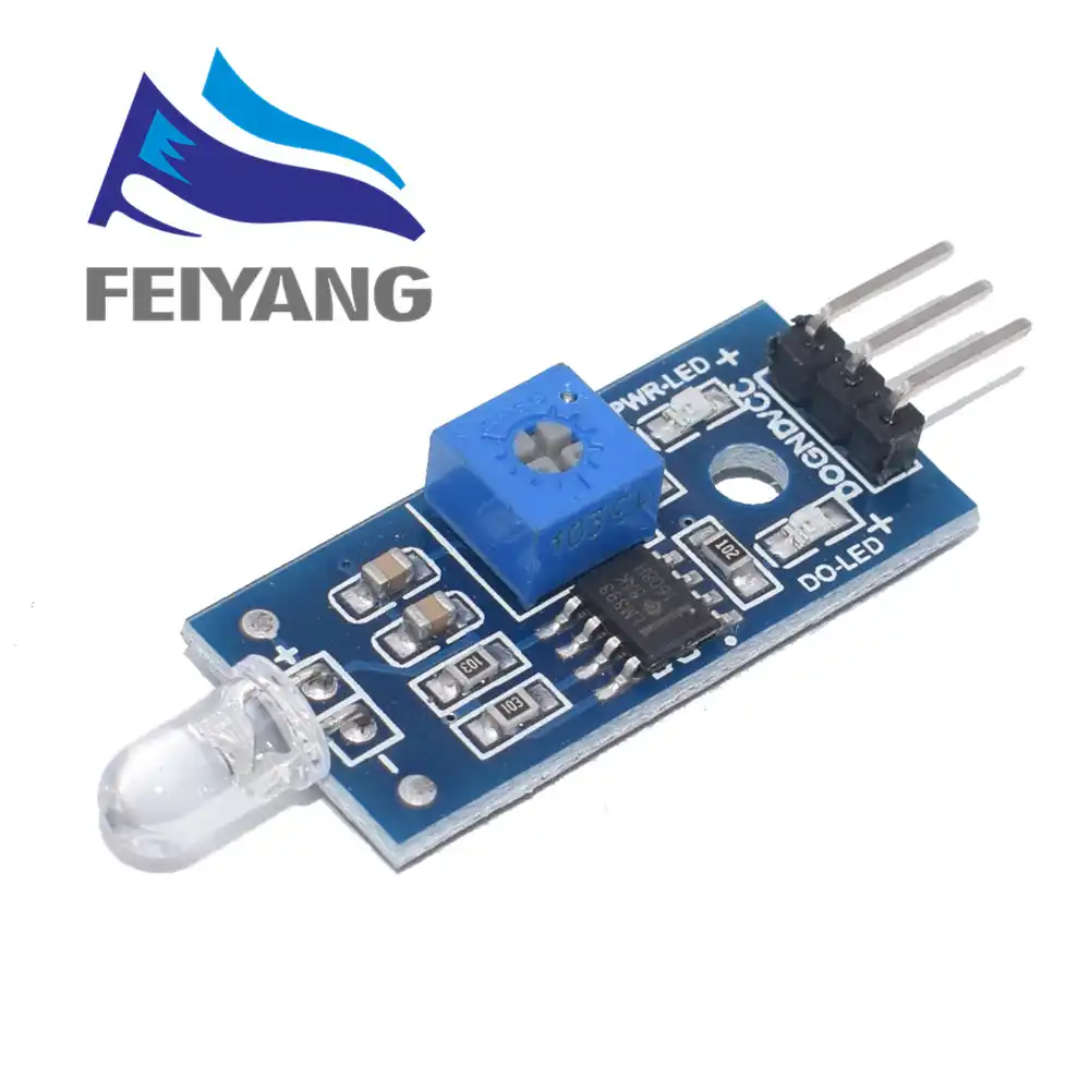
I’m trying to read Import kWh from an Elster A100C. I’m using the following sensor
I’m using a simple to sketch to get the information but I’m receiving garbage instead.
void setup() {
  // Open serial communications and wait for port to open:
  Serial.begin(2400);
  while (!Serial) {
    ; // wait for serial port to connect. Needed for native USB port only
  }
  Serial.println("Receptor Led");
}
int seg=0;
void loop() { // run over and over
seg++;
//delay(3);
  if(Serial.available()){
       byte a = Serial.read() &  0x7f; // cheap way of converting from 8N1 to 7E1 0x7F
       char b = a; // convert serial byte to ASCII character
       Serial.print(b);
  }
}
The Serial Output is something like this: UUUu}U_u_U__}_U}_}U_U_U_uu}}uu}UU}UUUU}U}_UUUUUU_U}UUUU}}}}UUUUU_u}uUUUUUUuU_UUUUUUU}UUUUUUUU}uU}UU}u_UUUuUuuU}UU}}}UUU}U_UUUU}UUUUUUUUu
I have also tried the elster_meter library ( Dave Berkeley) with no success.
Using an osciloscope, I could see that Elster’s irda led seems to be sending a lot of “01010101” which belongs to ASCII “U”
¿How can I convert this data to something “readable”?
Have you looked at section 13.1 on page 17 of the manual:
"The IrDA communications port provides one way communications,
transmitting a continuous data stream from the meter to an external
device. The data stream includes a start and end mechanism to
identify the start and end of the data stream (see Appendix A1 for
IrDA data format). An error-checking algorithm protects the integrity
of the data stream.
IrDA communications offer low cost, low power consumption and
high noise immunity.
A manufacturing option allows the port to be set to transmit at one
the following baud rates:
2400 baud (default rate)
4800 baud
9600 baud
Appendix A gives you (I think) everything you need to know about the message format - except of course the software to decode it.
I have also been reaching similar dead ends on this. Having read the Elster manual several times, and also tried contacting them to ask what frequency the IrDA transmits at. I have so far tried with a TSOP38238 and a modified Obstacle Avoidance sensor (cutting off the IR transmitter LED) .
I have used Arduino with both Dave Berkeley’s code and modifying the Arduino ir remote code myself switching between 2400, 4800 and 9600 in both cases as per the Elster range suggestions. And also, more currently on Raspberry Pi (mainly because the meter is a pain to get to, and certainly stand / stoop over at for any length of time, so the Pi gave me the ability to sit comfortably and modify paramters remotely. On the Pi I was trying the mode2 program with modifiers to give the raw output and wait for 100us+ intervals between characters (Elster manual suggestion). All of this seems to result in complete rubbish out the other end!! Dave Berkeley’s instructions are brilliant, however, as has been commented on accross a number of forums the IR receiver he suggests is no longer available, and I cannot fathom from the datasheet the frequency it recieves on!
A friend of mine has just offered me the use of his Oscilloscope, however, with the current situation he is now in a local lockdown, so we’ve considered it not particularly sensible for the moment!!
Can anyone help with this please? Just need to know if I have the right IR frequency (if not, which?!). I am assuming once on the right track everything else will just work!
This thread is now quite old but I’ve just got a smart meter, noticed that CTs are not that accurate and realised I could do better with the A100C’s IrDA port.
I have written Dave Berkeley’s code to a WeMos D1 mini and plugged it into a couple of IR receivers I have lying around. I don’t know what they are but they work with the standard pinout. I assume TSOP3248 or similar. Unfortunately I just get rubbish. The sensor is clearly seeing something when I wave it at the meter, but it’s just noise.
Has anyone made this work?
I noticed that the parts linked from the OEM blog to the OEM shop are no longer on offer.
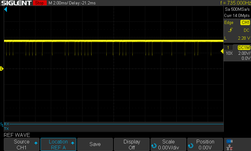
I have been experimenting with this, same problem I cant get it to work with an IR receiver that I have. I have managed to get a look at the signal though using a photodiode and it looks like the attached. I think that puts the fewquency of the pulses at something like 2.4kHz?
Maybe somebody who knows more about IR comms than me can point me in the right direction on what kind of signal this is?