I have been using a EmonTxV3.4CM to monitor our off grid solar power supply and consumption for two years. The EmonTx is located in a small metal shed approximately 80m away from the house where an emon base is used to receive and process the data.
The EmonTx antenna is located on the top of the metal shed and, with a ground plane under the emon base, the signal strength had been consistently around -68db. The emon base location was optimised for received signal strength previously.
Unfortunately with the installation of a new radio based internet service, the EmonTx signal has dropped of significantly. Now I am receiving only sporadic readings from the EmonT,x between 10min and 4hrs apart.
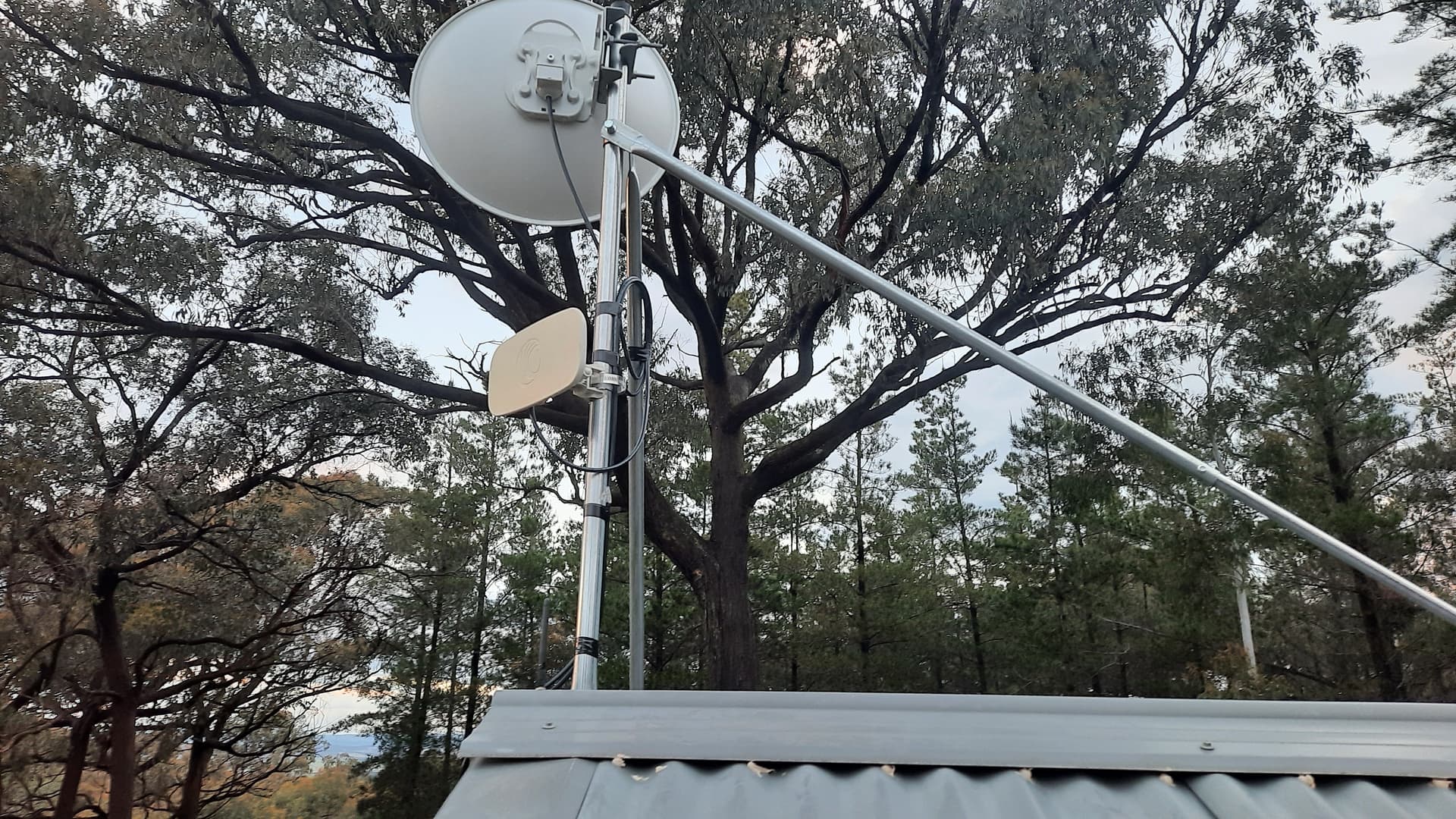
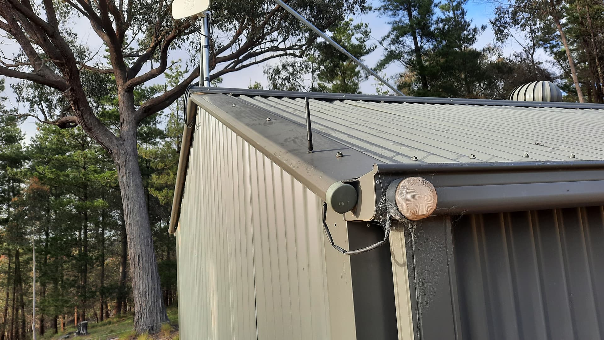
The following photos show the metal shed. The EmonTx antenna is the small stub antenna to the left of the base of the vertical support for the internet service radios. The emon base is in the direction where the lower of the two internet radios on the tripod is pointing.
Yes Robert, the tripod is new and the time the data stopped being reliable was during its installation.
The 433MHz antenna is approximately 6cm from the base of the tripod.
Hopefully @Bill.Thomson will confirm, but I think that’s de-tuned the antenna, or severely affected its radiation pattern (or both). One of them will have to move. I suggest moving the 433 MHz antenna down the roof by a metre or so.
(I don’t think much of the cables going over the sharp edge of that roof - it needs bending to give a rounded edge. Once you get water inside the sheath, it’s game over.)
Likely both. Antennas and metallic objects don’t play well together unless the length of said
objects and their spacing WRT the driven element is carefully controlled.
At least a metre. Two metres would be better. More would be better yet. i.e. Get it as far away as possible as the present feedline will allow.
To move the antenna any significant distance I will have to get a longer feedline. The present one is only 1m long.
I would appreciate your thoughts on placement.
Assuming I can get a suitable feedline (3-4m), there are several options for where to place the antenna:
one of the corners of the roof (1.8 and 4m remote),
the opposite end of the peak (3.5m remote but with the ventilator close behind),
at the top of the new tripod
on its own arm out from the roof
One option that would not involve replacing the feedline is to move the antenna to the side wall and mount it horizontally. I’m not sure of the pattern of radiated signal or any polarization effects, but the side of the shed does point to within 30deg of where the emon base is located.
How important is the orientation of the stub antenna? The ‘easy’ mounting points at the corners of the shed are inclined at a 30deg angle.
Noted Robert. The cables were initially run in front of the 433MHz antenna and so I did move them to see if there was any difference. There was a slight improvement. By slight, I mean the EmonTx signals started to be received (sporadically) again whereas previously they were not. I will run the cables over the rounded edge again when I move the 433MHz antenna.
Not a good idea. The radiation pattern is roughly doughnut shaped, with the antenna pointing up the hole in the middle. So if the antenna points straight towards the receiver, that’s the direction of minimum signal.
Looking straight down the antenna, the pattern is omni-directional, ignoring obstacles.
There will be losses in the feed, so you should aim for the minimum length possible consistent with getting it as far away from the mast as possible. It will be better to extend the sensor and power cables than the antenna feed.
If the wall is indeed offset ~30 degrees from the emonBase (even better if it’s closer to 45 degrees)
then mounting it horizontally should work OK.
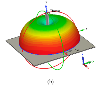
WRT the attached picture, the antenna is located on the Z axis. The ideal radiation angle is at
45 degrees above the X-Y plane. At 60 degrees of elevation, the radiated signal should be far
enough from the “blind cone” to as to be quite usable.
One other thing will need to be done if you mount the emonTx antenns horizontally.
You’ll need to orient the emonBase antenna horizontally as well. If one antenna is vertical and the
other horizontal, the signal strength wiil be reduced by 20 dB. That’s a loss factor of 100. i.e. not good. If you decide to try a horizontal mount, place the antennas so they are parallel to each other.
i.e. if the antenna on the side wall of your shed is pointing along a line that runs NE to SW, then position the emonBase antenna so it points NE to SW or SW to NE.
As long as both antennas are “tilted” the same amount, the actual angle they are at can be anything that facilitates easy mounting.
An inescapable law of physics. But, at 433 MHz, even crappy feedline like RG-58
(one of the lossier cables available) will work OK if the overall length is kept to ~3 metres or less.
The feedline to avoid, if at all possible is RG-174. At 440 MHz, RG-174 exhibits a loss of 25 db per
hundred feet. So even if the feedline is kept to say, 3 metres, the loss will be ~2.5 dB. 3 dB of loss
represents a drop in signal strength of 50% The same feedline made from RG-58 will have 1.04 dB
of loss at 440 MHz. Not good, but better than RG-174.
The idea is to use the best feedline you can, but if the overall length is kept short, even the “lossy stuff” can be used.
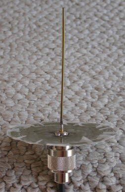
You’d actually be better off using something like this:
which is nothing more than an N connector with a piece of wire soldered into it, mounted on a
piece of sheet metal. Easy to make and outperforms a rubber duck, which is a compromise at best.
See Toothpick Monopole at the link below. (the correct length for 432.92 MHz is 165 mm)
If you can mount the connector directly in the sheet metal of your shed, you won’t need a separate
ground plane as shown in the picture, i.e. the shed’s wall will be the ground plane.
The only other thing you might need is an adapter. e.g. N connector to SMA.
The antenna you linked to gets its “gain” via a “flattened” radiation pattern.
(think of stepping on a doughnut) As a result, you’d likely see a decrease in signal strength.
i.e. it would be problematic at best to ensure the emonBase was in line with the part of that
antenna’s radiation pattern where the radiated signal is strongest.
You said that there is no wi-fi inside the shed but if the antenna for the internet connection is there, presumably there is some kind of internet equipment in the shed. If that can be accessed by a cable or any other way, then it might offer an easier and more reliable solution.
Sorry I’m having trouble understanding that. I know what POE is but surely a POE power supply needs to be connected to an ethernet cable (in the middle in fact) to inject the power into the cable? If so then there’s an ethernet cable in the shed and that could be put through a hub/switch. Then data from the emonTx could be collected locally and fed onto the ethernet.
For the benefit of someone who might be reading this thread, I moved the antenna today to a point close to the corner of the roof - about 1.6m from the tripod. Received signal strength now indicating a steady -68db.
I did learn a little more about radio signal propagation along the way and I am now keen to crack open a prefab antenna to see what is inside. The one I have looks shorter than 1/4 wavelength. A simple toothpick like the one Bill pointed to above might improve things a little more.
Thank you for your help.
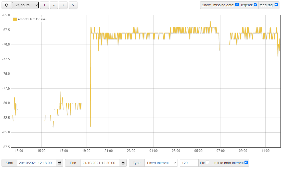
Unfortunately while the rssi levels look good (approx -68-70db) there have been a couple of periods where the data appears to have dropped out which I will now have to investigate.The image below shows the signal level improvement when the antenna was moved at about 1900 and the big dropout this morning at 0700.
Did you pick up on @djh asking about network within the hut? Where is the router for the Satellite Broadband?
If you have wired network, you could connect the TX up to a Pi (any version with an ethernet port) with the UART and send the data over the wired network.
The router is in the house 100m away and the wifi signal is not able to be accessed from within the metal shed. The two internet radios on the shed are on the ISP side of the router and within the power shed they are connected together by a single cat 5 cable.