Questions about USA system

Hi all. This project looks great, very impressive, and I’m really happy to be able to support open hardware. I’m trying to put together a system, and I’ve got a few questions. My background is I’m a non-electrical engineer, and I’m completely and shamefully lost when it comes to discussions about circuits. It’s best if I don’t solder or try to build electrical components, I would find local help if I needed to go that route.
So I’d like to start monitoring, I’ve got a solar PV system, so I’d like to track usage vs generation, and I’d also like to monitor one or two zones of my house. I live in New Orleans, so I’m trying to make this work on an American system. I’m planning on adding a bunch of temp sensors, but I’ll save that for another topic :wink:

I’m planning on getting an emonTx V3, and an emonBase.
I’ve considered alternatives to the base, like an android with AMP installed, or a Linux server I already have but doesn’t run 24/7, neither seem like good options (unless the emonTX can store several days worth of output, but I don’t believe it will)

I should probably mention that most of my big loads are going to be non-resistive, mostly a bunch of AC window units (heat pumps). My stove and water heater are gas, I do have a microwave, toaster, and a kettle that are used regularly.

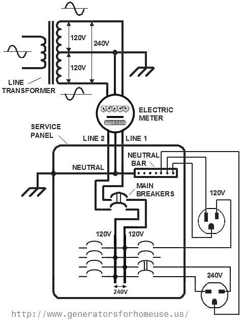
My panel is inside, 200A, the main switch is outside at the meter. There are a couple of feeds to subpanels and a solar PV system is connected to it.

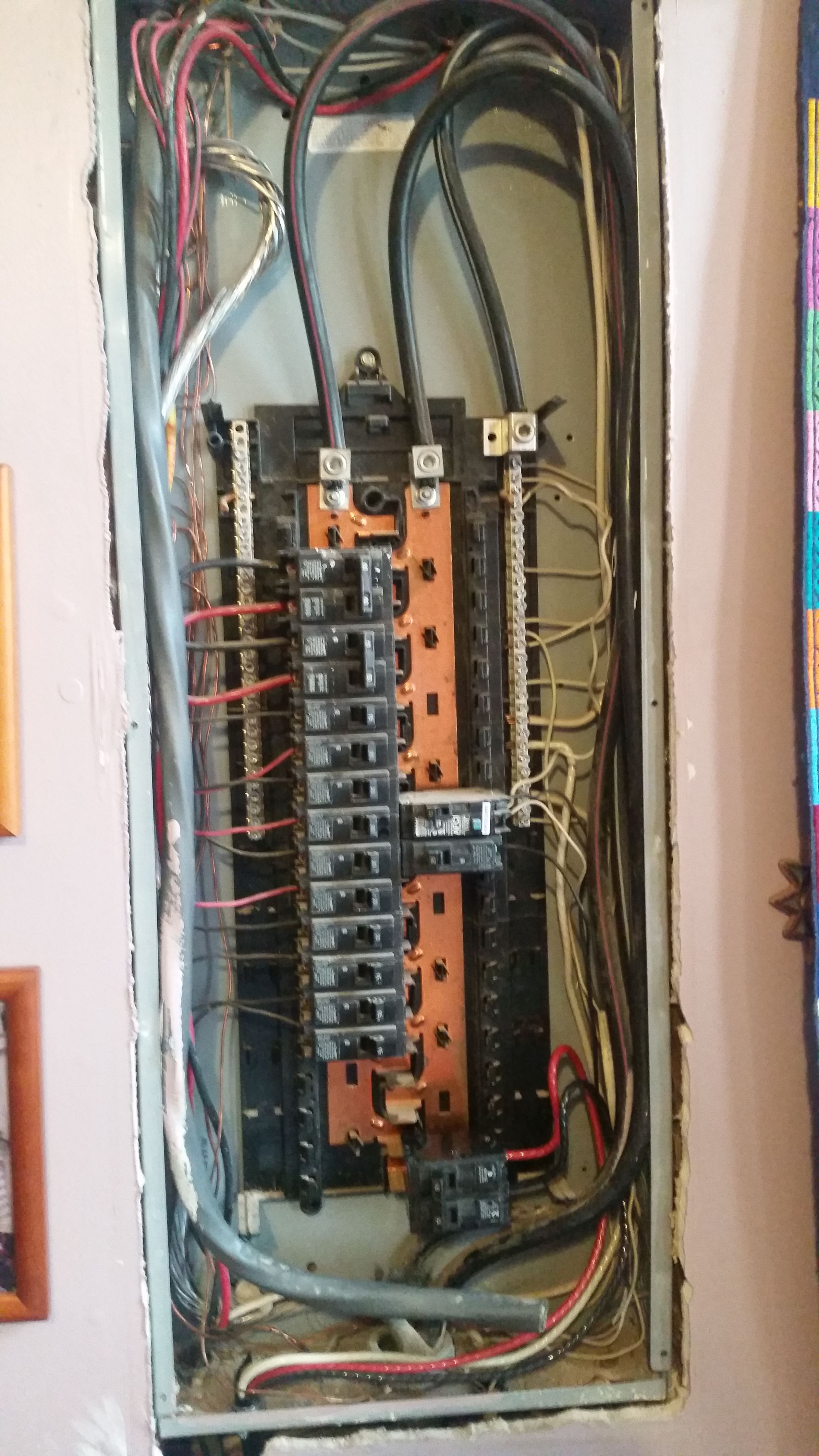
Here’s a pic of the box. I want to measure the main supply (200A, top), solar/PV (50A, bottom right), and the two upper left breakers (60A, 50A). I tried reading the ‘Use in North America’ page and it’s a bit over my head…will I need to put 2 CTs at the top and miss out on measuring one of the other breakers?
The CTs from OEM won’t fit over the main supply wires, they’re about 16mm, apparently 4/0 Al. It would be great if the project could find a good source to offer CTs to fit our big American wires :wink:
I haven’t found a 200A/1V except for the Wattcore that’s been mentioned, but I’m not sure if I need to fit an end on it. This sounds like the first choice, I just need to know how many I need.
I found a YHDC SCT019 (200A/0.33V) Can the output just be multiplied (by 3?) to get a good reading? Also not sure if this has the right cable end.
I also found YHDC SCT013s in 60A/1V, would those be more accurate? They are both +/-1%, but does that mean the inaccuracy is based off of the peak number, or are they the same? Would any adjustments need to be done to these for an accurate measurement? Or is there no advantage to these?
Looking at sensor port #4 on the emonTX, what happens when it exceeds 19A? I don’t expect that subpanel to reach that, but in case it does, are we talking the board gets fried, the port gets fried, or it just won’t register above that level?

One last question…power outages are somewhat frequent here, and I’ve got a grid tie PV system, so it stops producing when power goes out. Will the emonX units automatically turn on when power goes out, or does that have to be done manually?

Thanks for entertaining my questions.

Hello Alex,

I’m in Oklahoma. I can help you with items specific to a US installation, but I’ll defer the rest to Robert Wall.

The use in North America page has links to several sources of CTs that will fit 4/0 wire.
You may want to have a look at this article.

I’m very curious about your load center. I’ve never seen one with the bus bars exposed as they are in your picture.
Very unsafe situation you’ve got there unless your main breaker is switched off.

Thanks Bill. Good article. We’ve got pole transformers, I’ll check later if the stickers are readable. Going to 100A helps, those 200A Wattcores are pricey. I’m still not sure if I need one or two.
About my panel, this pic is with the cover plate removed, but are you saying there should still be something covering the bus bars?

for what it is worth my bus bar is exposed in the spots with no circuit breakers. When we moved in that was 6 to 8 empty spots (no breakers). Now it is one or two.

I’m curious why most all of the circuit breakers are on one side. It seems like the split phase would be unbalanced.

Given it’s totally enclosed when the cover is attached, that must be OK, or it likely never would have gotten installed. I’ve never seen one like that. Took me by surprise.

The bus bars are built such that even-numbered breakers are on one leg, and odd-numbered breakers are on the other leg. IOW, SOP to install them in position order.

Here’s a diagram:

my bad! you are correct!

I second that. If you go in there, you must be extremely careful. Not only is there a risk of electrocution if you slip, but if you short-circuit those bars, there’s likely to be molten copper flying about, and I wouldn’t like to be close if that happened.

Correct. The emonTx stores nothing. The data is launched, and as far as the emonTx is concerned, it is gone forever.

Yes, that will be two c.t’s. If you don’t want to connect them together, or you want to know the currents/powers in the two lines separately, that’s two inputs of your emonTx.

You only need one c.t. and one input for your PV infeed (as it’s 240 V) even though there is a neutral connection, it’s likely that the neutral current is small and represents the operating power for he electronics, so there’s little error in ignoring the imbalance in the two lines.

That leaves one input on your emonTx.
(You’ll want an a.c. adapter so that you know the direction of power flow (import or export) on your grid connection, and so that you’ll measure real power - which is what you pay for - in your pump loads.)

Yes, you’ll need a 3.5 mm stereo jack plug. I think plugs with screw connections exist, but you’ll need to check the size over the body diameter as the line of sockets on the emonTx are closely spaced and only just take a standard plug.

Yes[quote=“Bywaterian, post:1, topic:4533”]
to get a good reading?
[/quote]

No! You will be using a little less than one third of the range, in practice that means that you won’t be able to read small currents accurately if at all - the bottom limit will be 3 times higher than it would otherwise be.

For best accuracy, your c.t. wants to be a current output type, and you (almost certainly) need to change the burden resistor inside the emonTx. You probably don’t want to do that, even though for Bill and me, it’s a 2-minute job, therefore you need to choose a c.t. that’s as closely matched as possible to the circuit it is going on.

That accuracy is the slope over the working range. But at the ends, accuracy goes out of the window. At the top, the output droops as the c.t. saturates; at the bottom, the power needed to magnetise the core screws everything up.

At best, it reads incorrectly. At worst, it damages the ADC input and that probably means a new emonTx. We’ve never had a report (as far as I know) of one failing due to that, but I wouldn’t discount the possibility.

Having said that, changing the burden resistor can make the maximum input whatever you choose.

Yes, as soon as it is powered, it will wake up. So will your emon Raspberry Pi that is the emonBase - unless you have a little UPS for it.

[You lot have been busy while I’ve been typing!]

It caught me by surprise. I’ve been inside of several load centers, but have never seen one with the bus bars exposed like that. From what Jon mentions in his post above, it’s not unheard of. Just be aware of the danger involved with them exposed like that. You should be good to go with the way it is.

You can’t even get a “consumer unit” in the UK with exposed bars like that.

A more-or-less typical UK consumer unit with the front off:

Aren’t the emonPi and the emonBase two different units?

Not trying to nitpick, rather to avoid confusing the OP.

Arrgh!
Fingers typed not what brain was thinking. I’ve corrected it.

And note, the maximum currents are always determined by the combination of c.t. and burden resistor.
This is particularly important when you don’t have our ‘standard’ 100 A YHDC c.t. - then the inputs of the emonTx are not normally 100 A and 18.33 A.

Thanks for all the help everyone! It looks like I’ll have to get my friend with the electronics lab involved when they get back from vacation. They can help with the electronics parts that would take me hours to mess up.

Not sure how to quote while I’m typing on my phone, but it sounds like I can connect 2 100A CTs around my main cables (carefully with the main switch off) and combine them into a single plug?
And I can swap out a resistor on the TX board and remove the 19A limitation on #4.

Yes I’ve got an AC plug on my list. I also have a bunch of USB cables so I can run both units from what’s in my junk drawer.

Yes to both.

Beware! See ARCHIVE: : Not all USB power supplies are created the same

About my panel, it was a new install 10 years ago. This house was built in the 1880s, and was mid renovation when we got a hurricane. The owners gave up on it, and I bought it without walls and needing lots of work. The wiring was old (including knob and tube in the attic, probably not live) and I didn’t trust any of it or want to ever have to mess with it, so I had an electrician rewire the entire house, which let me move the panels inside (outside unprotected from the elements is common here) and set up subpanels.

Good info, thanks. Maybe I’ll use an old laptop as a power supply…I’ve got a few of those laying around. :smile:
Though that puts me back to considering a LAMP machine to replace the base unit, powering the TX. :thinking:

Anything other than a Raspberry Pi running off our SD Card image will require a bit of setting up. If you’re happy with that, then an old laptop is probably a good solution - you don’t need a top-notch machine.

We used to have instructions for setting up emonCMS on a LAMP machine, whether they have survived the recent migration exercise I’m not sure as I haven’t gone looking for them.

Here’s a video clip of molten copper flying about, of which Robert spoke.
Granted this is 3-phase AC at 480 Volts, but the same thing happening on a 240 Volt circuit, is surely as dangerous.

An electrical explosion, or “arc flash”, occurs when one or more high current arcs are created between energized electrical conductors or between an energized conductor and neutral (ground). Once initiated, the resulting arc(s) can bridge significant distances even though the voltage is relatively low. In the above demonstration, arcs were intentionally initiated by bridging #28 AWG wires across three bus bars in a testing laboratory. When power is applied, the wires immediately explode, forming a conductive plasma which evolve into high-current power arcs between the bus bars. In the above example, three one inch copper bus bars were separated by one inch, and were connected to a 480 volt open circuit source (a large delta-connected distribution transformer). During the 842 millisecond event, the average short circuit current was 17 kiloamperes, and the peak current exceeded 30 kiloamperes. The energy dissipated within a power arc is limited only by the fault current capability of the upstream power source and the duration before protective hardware “clears” (interrupts) the short circuit. In many low voltage (480 - 600 volt) electrical power distribution systems, fault currents can exceed 70,000 amps. The thermal energy liberated within these high-current arcs can be many tens of megawatts - equivalent to several sticks of dynamite. The arc core may reach 35,000 degrees F (four times the surface temperature of the sun!). As the arc “roots” vaporize portions of the copper bus bars, the copper vapor explosively expands to over 60,000 times its solid volume. The incandescent copper vapor rapidly combines with oxygen in the atmosphere, forming dense clouds of cupric oxide, blackening the air and covering nearby objects with black “soot”. Globules of molten copper are also violently ejected, showering the immediate vicinity with 2,000+ degree droplets at speeds that can approach 700 miles per hour.

Magnetic forces also propel the arc along the bus, extending it in the process. The high currents also generate huge magnetic forces that can bend thick bus bars or even rip them from their mountings, possibly creating additional shrapnel. Any unprotected individual unlucky enough to be anywhere near this event would be seriously injured or killed. Because of the extreme danger, most countries now require electrical workers to wear protective clothing and headgear whenever working near energized high-energy equipment.

From: High Voltage Arcs and Sparks Page

I’ve seen a few like that like that in Canada and thought the same. but that not even that bad I’ve seen worse design ones . but you see these type of fuse panels on 400amp main breaker- not so offend in regular residential of 200 amp. but generally I’ve seen them mostly on Mennonite or Huterite built houses and buildings - i do not know where they get them - probably buy them in US or Mexico and import them into Canada -

Nice video. Yeah, that looks suboptimal as an outcome to my experiment.

And that’s why I always avoided messing with this stuff. I’m content to burn myself in the normal ways (cooking, motor oil I thought was cool, etc.)