Hi Chaveiro, I will try to help a bit. I have a topic which I am going to post a few instructions on as I also want help similar to you and in return I hope someone can help me.  Here is the link: Modbus RTU (RS485) Instructions

Bill you received it today? It was fast!
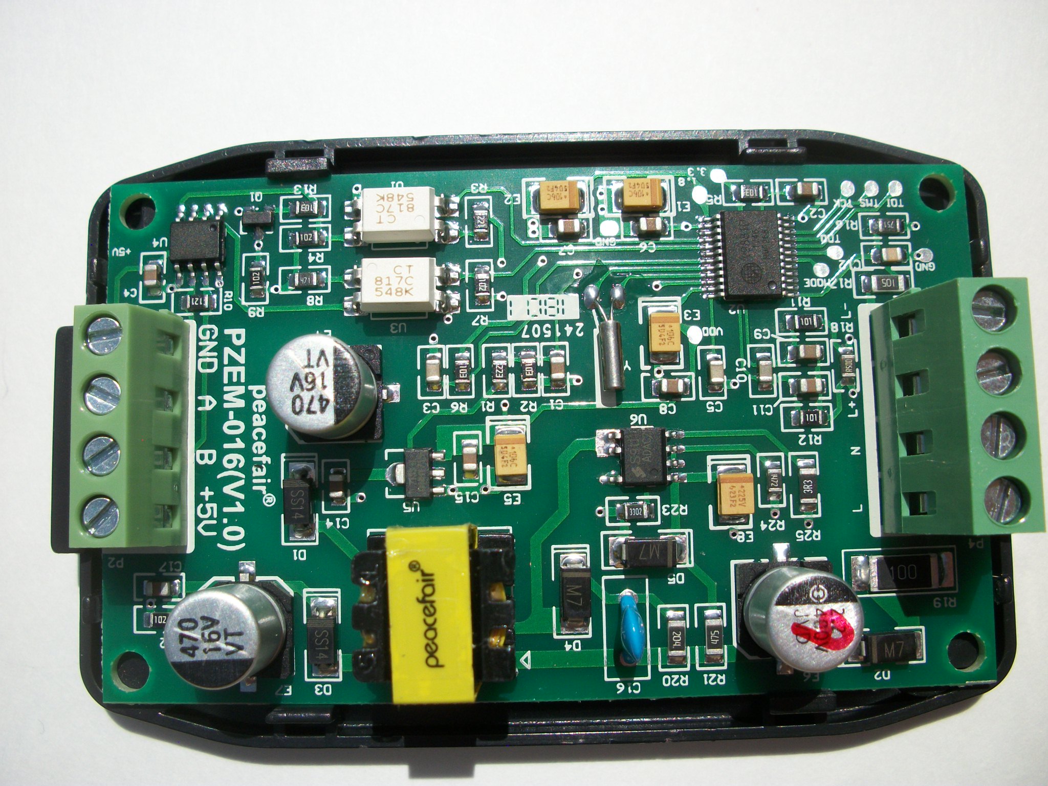
From what i’m seeing on the pcb, it does have galvanic isolation to the rs485 part.
Hi Nuno,
Surprised me too. I wasn’t expecting it for several more days.
It looks like it does have galvanic isolation.
I’ve got it working with a small python script. Wasn’t difficult, but then I’ve already got three other Modbus instruments, so it was just a matter of making some changes and she worked like a champ.
Here’s the script:
pzem-016.py.txt (859 Bytes)
APScheduler-2.1.2.tar.gz (40.8 KB)
minimalmodbus.zip (116.3 KB)
It’s very basic. Doesn’t do anything but read the registers and print their contents.
As written, it needs minimalmodbus and Advanced Python Scheduler v2.12
You dont have to use APS. I use it to read my other meters every 5 seconds, so I left it in the script.
Any loop construct will work.
I’m still waiting for my order…
Sure, please post your script or a link to github.
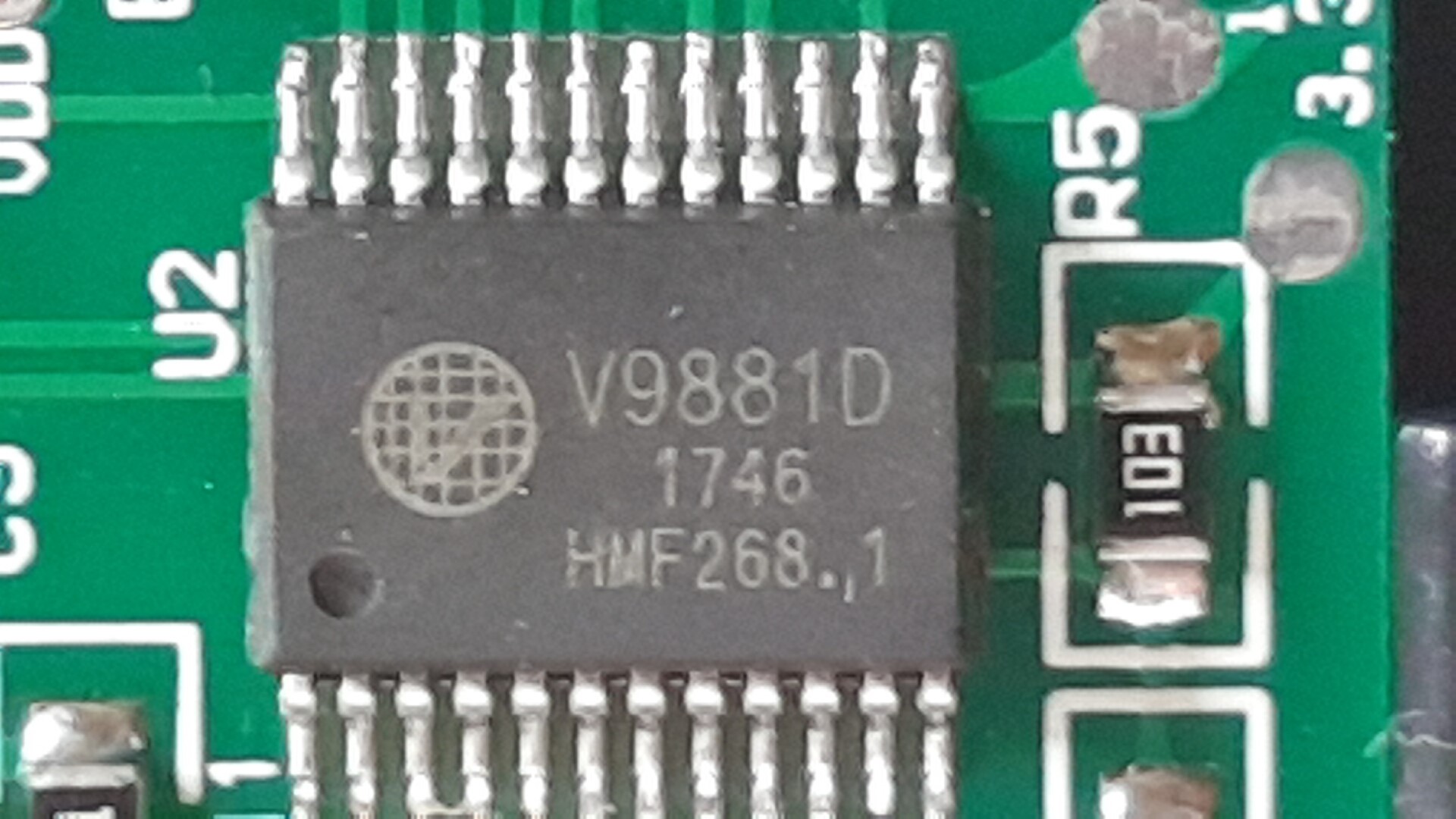
So I guess it must be U2 that does all the maths. Can you tell what it is?
I set my camera to 12 MP in the hopes of being able to enlarge the picture to read the characters on the chip, but no joy. The markings are very faint. I had it in full sunlight, but still no help. Bummer.
Ah well, I guess at $12 per unit, there’s not a lot of incentive to reverse engineer it ;-).
PB and I thought the same thing, i.e even if it’s junk, at that price it’s a throw-away item.
So far, it seems to be fairly accurate. I have a 40 W incandescent lamp as a load with 10 turns wrapped through the CT window and it’s reading 429.1 W, 3.57 A, 120.2 V.
But hey, whatta ya want fer 12 bucks, right? ![]()
So internally consistent at least. Do you have a trusted meter you can compare those numbers with?
I guess I could buy one and stick it on the calibrator to give it a good run for its money, but I doubt my calibrator’s V output would have enough ousht to drive its power supply. I needed a separate V input on my monitor for that reason. One V input to power the unit, and 3V inputs to measure. Once installed, you can daisy chain the first off any of the other three but when calibrating, just having the power supply attached to the calibrator’s V output distorts the signal (as do many 9VAC wall-warts).
The Fluke 27 DMM I have (calibration unknown) consistently reads 0.4 to 0.5 V higher than the Modbus meter.
But… I do have access to TMDE that gets calibrated anually.
I’ll take it to work with me tonight and check it against a a Fluke 289 true RMS DMM.
Whatever it is, it looks like you flash it via JTAG, note the TDI TMS TCK pins in the bottom left corner. And you’d need an isolated programmer since all that sits on the scarey side of the barrier.
I noticed they used an STM32 with an ST-LINK header in one of their products:
https://www.webx.dk/oz2cpu/energy-meter/energy-meter.htm
That too would need an isolated STLINK programmer. Actually, that entire hack project is very dangerous (they do mention it in the fine print). They’re wiring up external hardware to the live side of the barrier so all of the display hardware is live.
Now, speaking of STM32s… what’s been happening out there in OEM / STM32 land?
Got one of those too.
Version 13 of your script is the newest thing I’ve seen…
Looks like my 27 isn’t too far off. (can’t complan too much, it was a freebie)
Compared to a calibrated Fluke 289, the unit reads a consistent 0.3 Volts low.
Mine arrived yesterday,
It’s a “Vango” V9881D (link to datasheet http://www.vangotech.com/tw/uploadpic/152783461494.pdf)
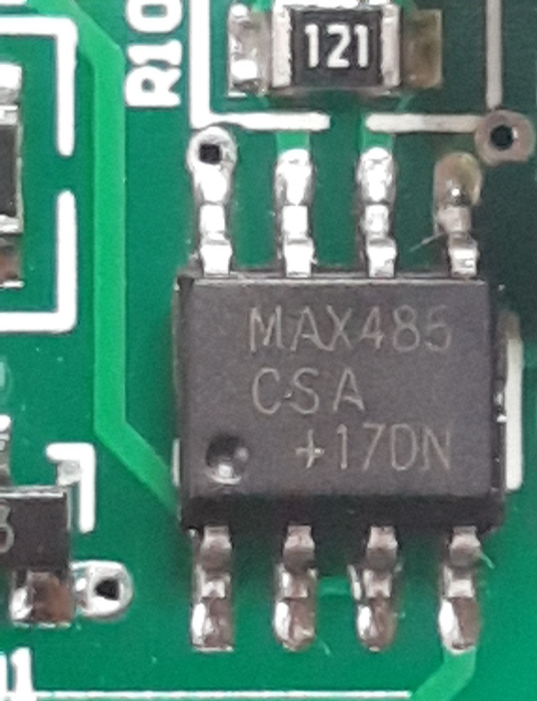
the rs485 transceiver is a Maxim MAX485 (link to datasheet https://datasheets.maximintegrated.com/en/ds/MAX1487-MAX491.pdf). The spec of a MAX485 is a “whole unit” so there would only be a maximum of 31 of these (plus a master) in a single rs485 chain (without repeaters).
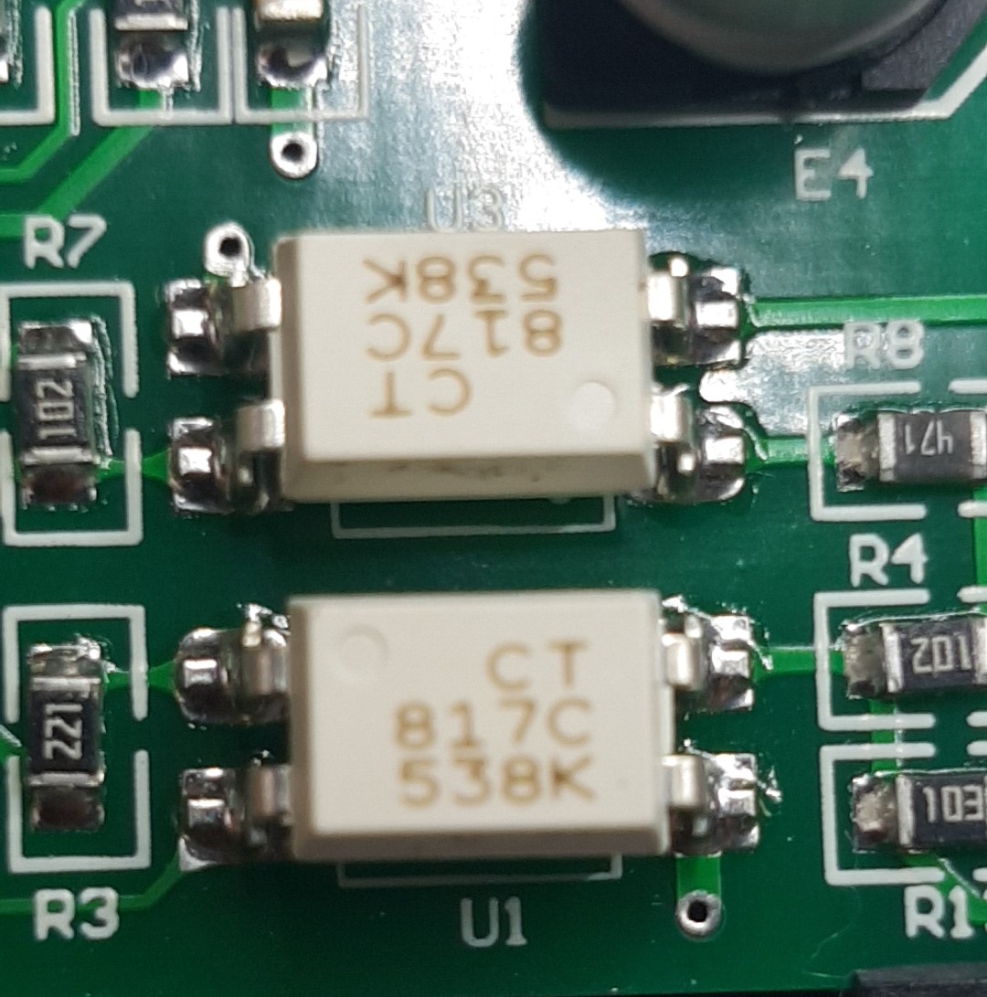
the isolation is done by a pair of CT Micro CT817C’s (link to datasheet │CT Micro International Corporation│)
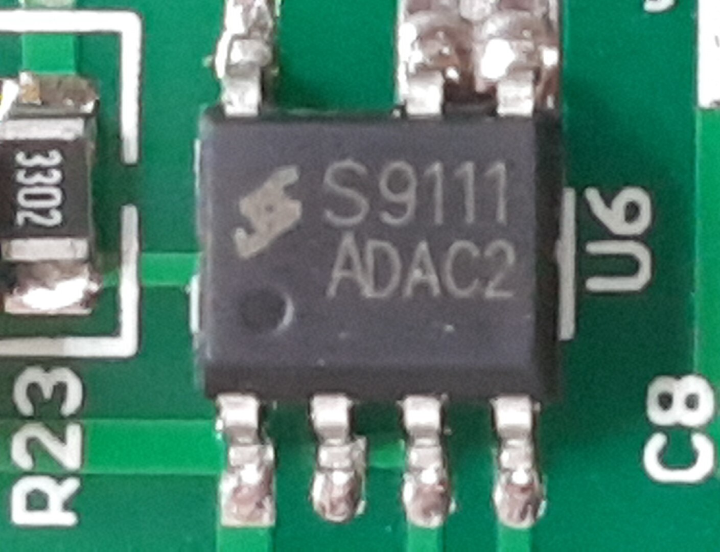
there is also a “S9111 ADAC2” that I didn’t find any info on, but it’s position and tracks lead me to suspect it might have something do with creating the 5v DC supply.
I haven’t hooked up to a load yet, but I did try communicating with just the rs485 and 240v connected and it seems to communicate fine with the “one to one” windows utility in the zip posted earlier in this thread.
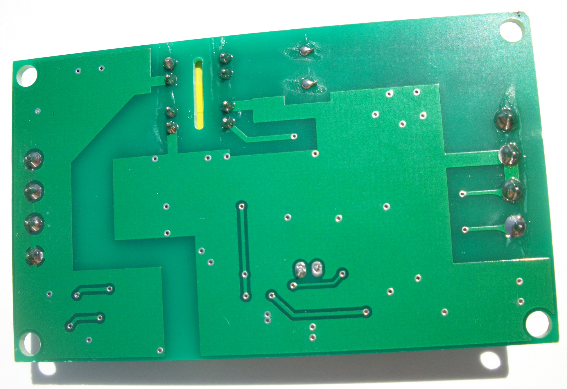
The terminal blocks are a tad el cheapo (as expected) but aside from that it seems “ok” build wise. However IMO the connection map on the underside can be a bit misleading as it is correct whilst looking at the underside, but it needs inverting when looking at the module from the top which is where the terminal screws are (despite the map possibly suggesting otherwise), that’s not an issue when the unit is loose in your hand, but if mounted and you’re using an online map or looking at another unit, you could get it wrong.
I am going to try writing a python script a little later (if I don’t get otherwise engrossed with something else), I’ll post here what I learn.
Hi Paul,
Good pics. Your camera is better than mine. ![]()
Looks like it’s got the goods. I notice they too calibrate phase error at a 60° phase shift, so you may not want to put it into calibration mode unless you’ve got some equipment that can do that.
It’s just a regular 12mp camera on a Galaxy S7, but I use a magnifier app for such occasions (https://play.google.com/store/apps/details?id=com.softdx.quickmagnifier). The hardest part to using it is keeping your hand steady, it’s like I’ve got a serious case of “the morning after the night before” shakes.
Luckily it isn’t so easy to do (without the supplied utility) once they are in service, if there are more than one of them connected you cannot put it in calibration mode as it uses a generic slave address (regardless of the one programmed) that all of the devices will try to respond to. It can only be calibrated in a “one on one” connection.
Whilst looking at some other devices such as this one
I noticed that some have separate import and export energy totals which makes perfect sense and would be essential for some applications eg PV inverter and grid connections. From what I’ve read all the values from the pzem’s are unsigned so both import and export will ramp up the energy total and there is no easy way to tell the direction of travel of the power value to calculate it outside the device.
The example device I linked above should work work really well for users with a excess PV diverter as “true” export and import values will be of much greater value than the “net per 10s” we’re used to which looses all the data for energy in the “sweet spot” oscillating. I’m thinking of trying one of those too as the din rail mount and separate import/export totals might be worth the price difference (< x2).
Although that one will do up to 45A without a CT (which is a plus IMO), something like the one below with a 100A CT might be more appropriate for a main grid connection although this one is unfortunately considerably dearer (~ x4).
[edit - hope nobody minds, I’m going to add some links here to refer back to as it seems that last device goes under a couple of names and there is conflicting info about whether it is 60A or 100A]
EM115-MOD (60A CT)
Page Not Found - Aliexpress.com
http://a2.leadongcdn.com/attachment/7ripKBloSRjlmnkoRiwS77gwbf3znq/EM115-Mod-.pdf
EM115-MOD (100A CT)
https://meters.co.uk/wp-content/uploads/2018/05/EM115-MOD-.pdf
OB115-MOD (100A CT)
OB115-MOD (45A Direct)
https://owen-brothers.com/media/wysiwyg/OB115_User_Manual_2016_v1.2.pdf
DDS238-1 ZN (45A Direct)
DDS238-1 ZN (32A Direct)
Modbus - KWh meter - DDS238-1 ZN
single phase static watt hour meter | Electricity Meter
China Circuit Breaker Manufacturer, AC Contactor, Thermal Relay Supplier - XIAN GOODNESS IMP. AND EXP. CO., LTD. ($1.90~$2.40 volume pricing!!!)
DRS-205C (32/45A Direct)
Page Not Found - Aliexpress.com
http://q.zvk9.com/1200/2017/12/12/2.0%20DRS-205C%20MBus%20Protocol%20V1.1.pdf
http://q.zvk9.com/1200/2017/12/12/DRS-205C%20MODBUS%20user%20manual.pdf
DRS-2DM(60/80/100 Direct 2 tariff)
Page Not Found - Aliexpress.com
HTB1ZGClHpXXXXamXVXX.PRXFXXXv.pdf (257.4 KB)