Pulse input interference on Emonpi and TX

I have been running an Emonpi and 2x TX(v3)s for a couple of years without issue other than the odd self-inflicted one. The units (all shop sourced - including adapters etc- , SD emonSD-03May16, Emoncms 9.9.5 ) are monitoring a stand alone, off-grid system, all AC coupled (obviously with the exception of battery storage) as follows:
Emonpi - PV and Wind Turbine generation, 6x temperatures (wired via breakout board and 12m unshielded patch cable)
TX3 - Genset generation, three distribution circuits, 6x temperatures (wired via breakout board and 12m unshielded patch cable)
TX4 - three diversion load circuits, 1x temperature (1m RJ45 cable)
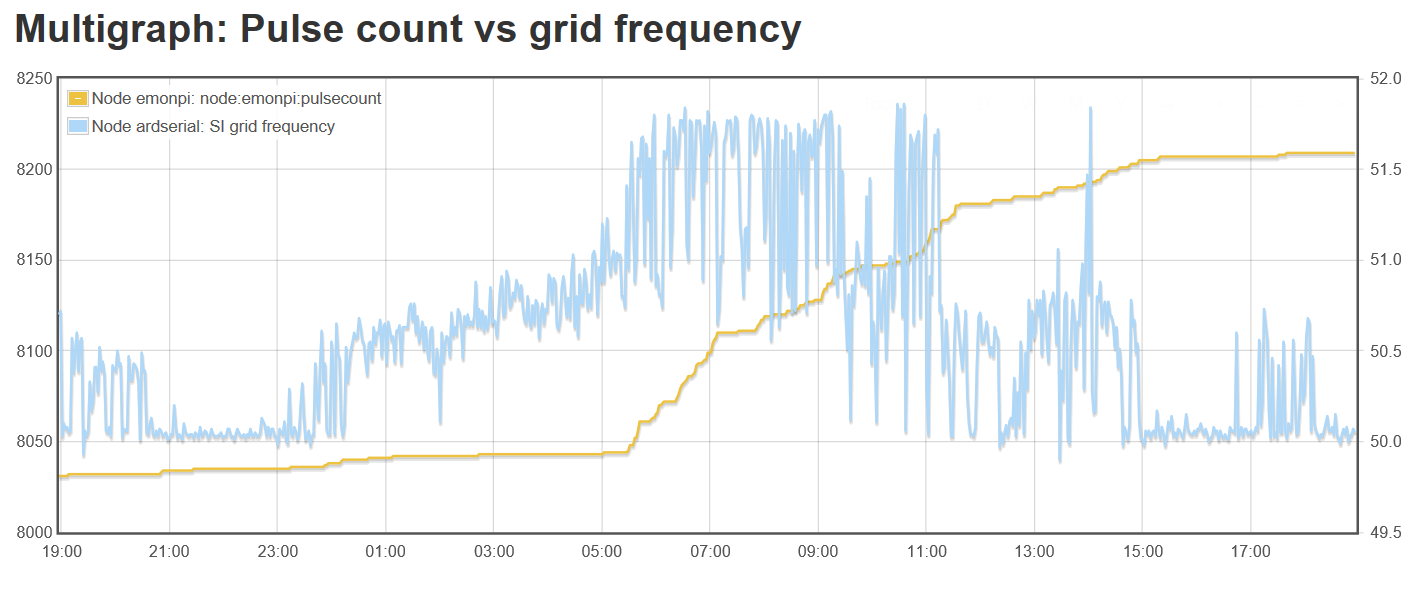
There is an Arduino monitoring AC frequency and Battery bank voltage and sending via serial to the Emonpi. Edits in emonhub for this to work are the only changes I have made to the units.

The entire off-grid system is a little unusual with a number of potential issues that would not feature in normal installations but there has been no apparent conflict with the Emon set-up so far (at least not that I have perceived).

The pulse inputs have always incremented on the Emonpi and TX3 but not the TX4 which has the single temperature sensor and short cable. This has not been an issue since I previously had no use for these inputs and simply ignored them.

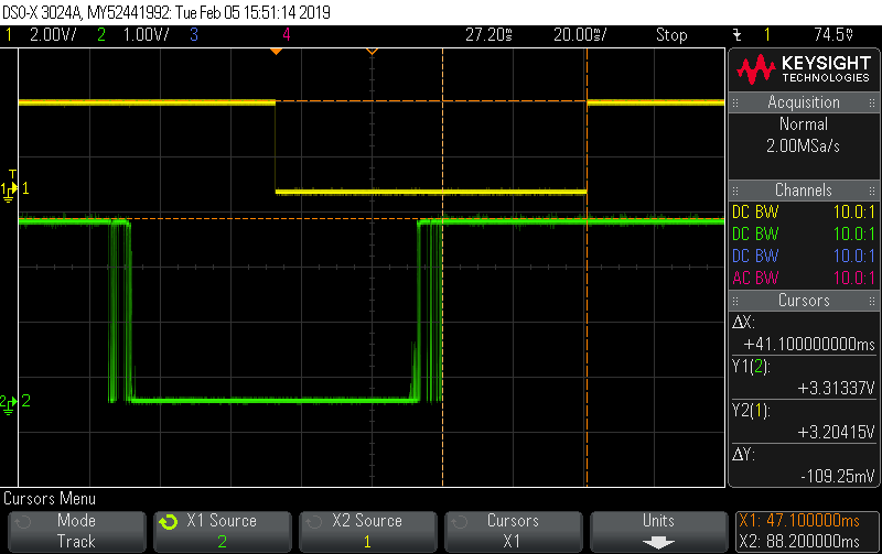
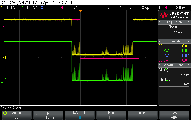
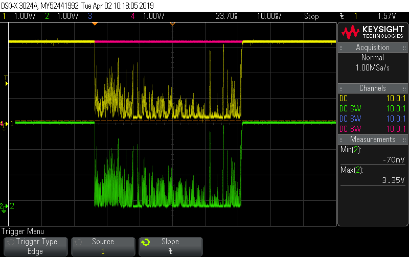
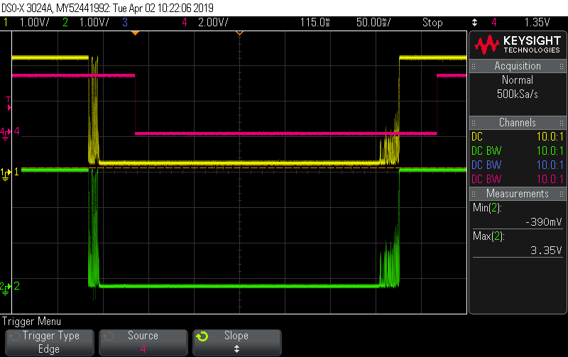
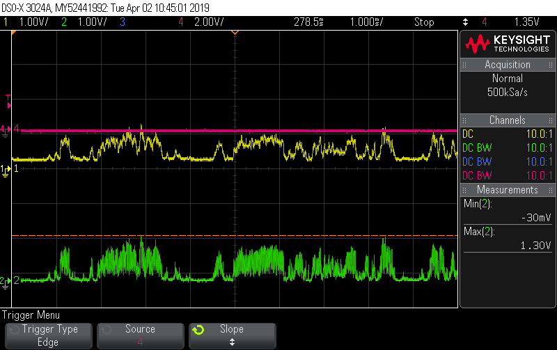
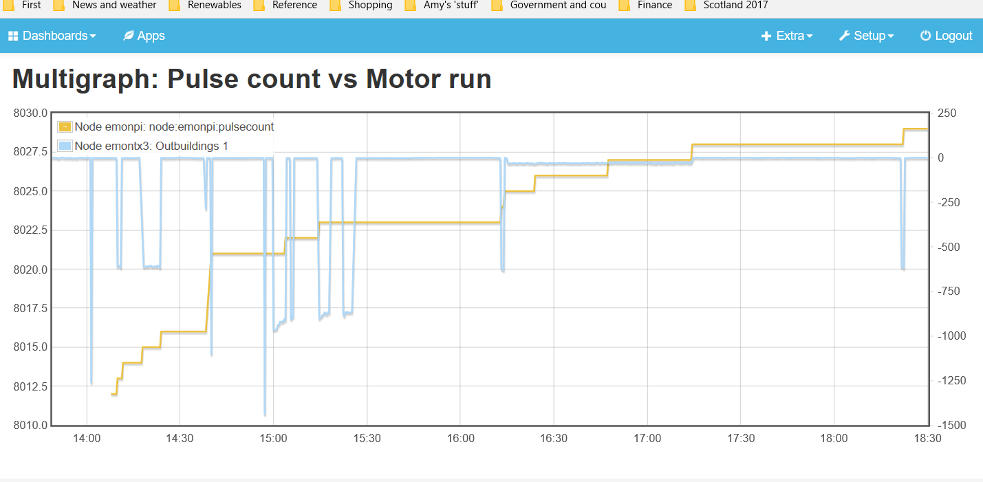
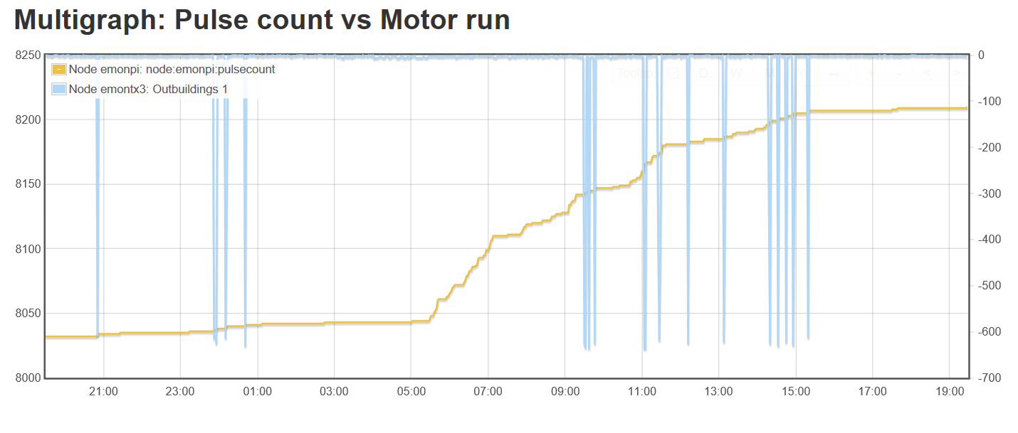
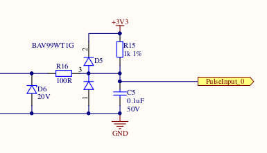
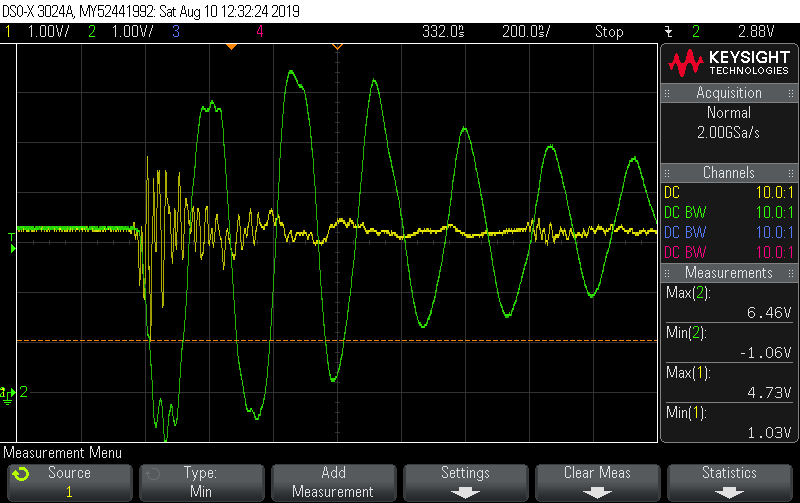
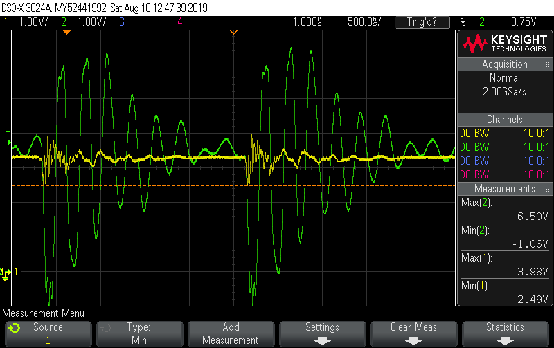
Recently I acquired a s/h Sontex 749 heat meter and although I have been manually recording heat output (the unit itself is working fine) I thought it would be useful to integrate this into the Emon set-up utilising the meter’s wired, open drain, pulse output. I wired the Sontex output and GND to the 2nd breakout RJ45 ( wired IRQ and GND only) connected to the Emonpi and pulses register fine, corresponding with the meter’s display. There are, however, still the “spurious” pulses registering. These are apparently directly related to motor activity on a local socket circuit, in particular the 700W house supply water pump but also some power tools (eg mitre saw). Pulse generation correlates with these motors activating.

Having read other posts on the subject of spurious pulse counting (and, frankly, not entirely understood it all) I assumed interference picked up by the patch cabling which was in close proximity (6") to the distribution circuits at some points. However neither re-routing the cable to give a separation from circuits of about 2’ nor connecting the pulse only (no temperature sensors or breakout board) with a different “shielded” cable (admittedly of unknown actual quality!), and with even greater separation (4-5’), made any difference.

I have now connected the meter to a EmonTH (as per wiki instructions) and this is giving a perfect and “clean” pulse record. Problem solved but…

Am I right in assuming that cable interference was probably the problem or is there something fundamental I am missing?

It seems a shame to not be able to use the three existing potential pulse inputs of the Emonpi and TXs - I intend installing at least one other heat/flow meter in the future.

Is there something relatively simple and inexpensive I can do about interference? There will always be motors of various sizes/types/age in use on the sockets circuits - note that low power motors such as heating circ pumps do not cause a problem nor do large resistive loads (including phase angle diversions).

I can not completely move the cabling much further away from circuits as all cabling needs to be routed into the same area around the main inverters and grid CU where the Emon units also need to be. Temperature sensors to the Emonpi and TX take priority over any meter pulse counting. I am loath to acquire some high quality shielded cable unless that will definitely work and acquiring an extra TH unit seems a bit of a waste for just a single pulse input.

Note my expertise in this area of electronics, particularly EMI and the like, is very limited and I am just learning as the need arises. Apologies if this has been bit long winded.

Is the emonTH (that doesn’t pick up the interference) battery-powered?

Your TX4 is using standard c.t’s - how is it getting its power to operate?

Generally speaking, you’ve tried all the right things regarding cabling, and I would have expected what you’ve done to make a difference.

The Sontex output is open-drain - what else do you know about it? What current is it capable of handling? I’m going to suggest a stronger pull-up resistor - better than the internal one of the '328P pulse input, but I need a bit more information.

Although it’s probable that the interfering pulses are coming in via the pulse input and its wiring, it was just a thought that it may be mains pickup via another route. If you have a spare 5 V d.c. USB adapter, it might be worth trying that to see if it has any effect. I’d hope not, but interference is funny stuff.

Another way it could be mains-related is if the GND connection between the Sontex and the emonTX isn’t good enough in the presence of the interference to keep the two at the same voltage. I presume the Sontex is mains-powered, does the emonTx have a connection to earth (or mains neutral) anywhere other than the a.c. adapter/USB adapter - via the serial data port for example?

The real solution of course isn’t to stop the emonTx picking up the interference, but to stop it being generated at source. Does your water pump have any filtering/suppression on the switch contacts? and the mitre saw? That means dealing with all sources individually, but it’s something that ought to be done anyway. Something like
https://cpc.farnell.com/ampohm-wound-products/fe-sp-hdr23-100-100/contact-suppressor-0-1uf-100r/dp/FT00715
across the switch contacts may be enough.

Just to throw another idea into the ring (or rule it out at least). How close to each other are all these points of interest?

Vibration?

RJ45’s (among other connector types) are not as good as proper solid connections, could you try using the screw terms (as per the emonTH) rather than the RJ45 for the pulse input at the emonTx?

A good ole shake of the wiring etc (whilst the motors are not running) should rule this possibility out if no pulses are detected.

Interesting thought - but I’d have thought power tools would normally be used some distance away and that vibration wouldn’t be a likely suspect.

That maybe (and most likely is) the case, but ya never know.

I think I just dislike RJ45’s for this type of job. But the wider point is any connection issues at all can introduce extra pulse counts.

As you know it’s the number of changes the emonTx interprets as pulses that gets counted, not necessarily the number of pulses that the device generates. So any suspect connections can play havoc and that might even be dependent on “outside influence” and not always a permanent fault eg vibration/movement/temperature etc

As the pull-up is inside the processor, and the output is (presumably) a pull-down on a pulse, it’s hard to see how a spurious pulse can be generated unless a break in continuity divides a genuine 500 ms pulse up - that could be cured by increasing the 80 - 120 ms lock-out that the software imposes. But if the output is normally-low, then vibration could easily be the cause, and most likely the only cause. In that case, wiring the Sontex to the emonTx screw terminals rather than to the RJ45 is an easy cure.

So my feeling (and it is only a feeling) is that it’s either a grounding problem between the heat meter and emonTx, or a massive spike coming in via the emonTx power supply.
If it’s still pick-up via the cabling, a stronger pull-up should lower the impedance and help.

But I discount nothing.

Many thanks for those replies gents. To answer some of the queries:

Is the emonTH (that doesn’t pick up the interference) battery-powered?
Yes

Your TX4 is using standard c.t’s - how is it getting its power to operate?
Standard OEM CTs and mains adapter.

The Sontex output is open-drain - what else do you know about it?
Battery powered (Lithium 3Vdc) with only the following from the datasheet:
Pulse output Open drain (MOS Transistor) 1 Hz, 500 ms Vccmax : 35 VDC ; Iccmax : 25mA

I’m going to suggest a stronger pull-up resistor - better than the internal one of the '328P pulse input, but I need a bit more information.
I have tried a very crude breadboard arrangement with 10k and less resistors which seemed to make no difference. I think I wired them up correctly but, as I said - I’m only learning as I go!

does the emonTx have a connection to earth (or mains neutral) anywhere other than the a.c. adapter/USB adapter - via the serial data port for example?
No connections other than the AC adapter on the TXs. The Emonpi has USB connection to the Arduino and also ethernet in from a powerline adapter (a rather extended temporary solution soon to be replaced with direct connection to the router when I have finished pulling the cable). Note that I have tried the pulse only (no breakout board and temp sensors) connection via “shielded” cable on both of the TXs and the Emonpi - same result.

Vibration?
RJ45’s (among other connector types) are not as good as proper solid connections, could you try using the screw terms (as per the emonTH) rather than the RJ45 for the pulse input at the emonTx?
I had considered this (mentioned on another post) as the Sontex and patch cabling were in contact with tanks and pipework served by the water pump. Moved everything but same result and then tested with rather more distant but similar draw motors (mitre saw, pressure washer etc) and again same result. I’m not discounting vibration but I positioned the pressure washer some 20m away outside the building! The patch wiring has had quite a lot of “disturbance” while I’ve been wrestling with all this, although maybe a bit short of a good ole shake - still only records pulses associated with motors.

With regard to mains pick-up - this is an off-grid set-up with frequency shift deliberately incorporated and also some voltage variation possible at times, the inverters are good but not perfect. I don’t know how this may affect power supply to the Emonpi and TXs but I have seen no other signs to suspect it might. I haven’t been able to find any correlation between those elements and spurious pulses but I am no expert. I can provide any number of different scenario graphs from Emoncms data and even the main inverters if it would help.

The real solution of course isn’t to stop the emonTx picking up the interference, but to stop it being generated at source. Does your water pump have any filtering/suppression on the switch contacts? and the mitre saw? That means dealing with all sources individually, but it’s something that ought to be done anyway.
Water pump is a cheap and cheerful one (although given 9 years good service) so I doubt it has any filtering. Not sure about any of the other offending motors - I will try and find out.
Dealing with each source may be the best solution but there are quite a few and potentially others not tried yet.

I would have suggested a lot less than 10 kΩ, but unfortunately the a.c. adapter can’t supply enough current for that as well as a temperature sensor. If a pulse happened to come in just as the emonTx was transmitting, when the mains voltage was low, it’s possible that the emonTx would crash. This is where the USB d.c. power supply would help.

Can you spell out exactly what you mean by “associated”. Is it a single extra pulse or a burst, at switch-on, switch-off or randomly whilst running?

Is this code still the current state of play for debouncing:

// The interrupt routine - runs each time a falling edge of a pulse is detected
void onPulse()                  
{  
  if ( (millis() - pulsetime) > min_pulsewidth) {
    pulseCount++;					//calculate wh elapsed from time between pulses 
  }
 pulsetime=millis(); 	
}

The problem with that approach is that it de-bounces, but it doesn’t de-glitch. I can’t recall how fast AVR’s edge detectors are but they’ll be very fast. The stm32 edge detector promises to latch pulses as brief as 10 nsecs. That’s handy when you need to capture genuine short pulses from another IC on the board, but not so useful when you’ve got 10m of cable driving the pin and large electric motors inducing glitches. A 10 nsec (or even 10 usec) pulse is not a genuine pulse in this context but will be counted by that code above. That code will ensure you only count one of them but that’s one too many.

The approach I take is: after things kick off, wait for the dust to settle (no transitions for 40 msecs) then look at the pin state. If it’s the same as it was before anything happened then declare it a glitch and ignore it all, otherwise declare it as an edge. So the 40 msecs not only dictates how frequently pulses can arrive, but also how prolonged they have to be before being counted.

I’ve coded that on the stm32 so the code isn’t directly relevant to the Arduino context but it’s pretty easy to describe in pseudo code. It does require you to enable interrupts on both falling and rising edges - you can do that in AVR land with the PinChange interrupt.

either_edge_isr()
  current_state = read_pin();
  if (current_state == output_state)
    last_edge = 0;                                          // stop the timer
  else
    last_edge = millis();                                 // start the timer
  pulse_input = current_state;

main loop:
  if (last_edge  &&  millis() - last_edge > 40)    //  has timer expired?
    last_edge = 0;                                               // stop timer
    output_state = pulse_input;                          // promote out filtered output state
    if (output_state == 0)                                    // count falling edges of filtered output
      pulse_count++;

I’ve left out details about capturing the volatile ISR state in a consistent fashion, but normal rules apply there. This code also relies on a low latency main loop. If you main loop latency is in the tens of msecs, then the 40 msecs becomes 50 or 60 which is probably still ok. But if your main loop can stall for seconds then your debounce period becomes seconds and you’re sure to lose pulses. I run a tight main loop, with a tight h/w watchdog set to police it, but my plan B if ever I had to surrender that would be to use a h/w countdown timer instead of a s/w timer. Then 40 msecs after the last edge, the timer ISR will run and do what I do above in the main loop code.

output_state above is just a s/w concept, it’s the filtered output of the pulse input, but if you have a spare IO pin then it’s easy enough to output it so you can view the filter in action. In these two pics, Green is the noisy unfiltered pulse input, and Yellow is s/w derived output_state - and it’s’ the Yellow falling edges that get counted:


Given those either-edge ISRs can arrive as frequently as every 10 nsecs (or whatever speed your edge-detector promises) it’s also worth putting a real h/w LPF on the input to protect against a rogue input bringing the processor to its knees.

In the following pics, Green is the unfiltered input, Yellow is the input after the h/w LPF and Red is output_state (the s/w filtered output that drives the pulse counter). You can see in the second pic no pulse was counted at all because even though all that noise dragged on for ~40 msecs it was never quiet for 40 msecs so it was all deemed to be glitches and done away with.


That method, as far as I’m aware, has been adopted universally.

Universally as in universally in OEM land, or universally universally?

Maxim have a pretty good paper on debouncing and include the need for de-glitching:

In addition to bounce, switches and digital systems have other annoying habits. Strange things happen, for example, when you run switch wiring in a noisy industrial environment. An open switch has high impedance by definition, so interfering signals have an easy load to work against. Any noise impulse that is capacitively or inductively coupled to the switch wiring can cause phantom switch closures.

That.

Hence my desire to lower the value of the pull-up resistor to lower the voltage that’s (presumably - I’m not sure of the mechanism yet) coupled in.

A question I forgot to ask @jingy:
Is the GND connection on the heat meter connected to the pipework - and is that earthed anywhere? (If you’re in the UK - your IP address says yes but profile doesn’t tell me - then it should be.)

Phew - you lost me a bit there gents :exploding_head:

Can you spell out exactly what you mean by “associated”. Is it a single extra pulse or a burst, at switch-on, switch-off or randomly whilst running?
Single pulses incrementing uniformly while the motor is running as I recall. These are not motors that generally run in short bursts though (water pump is pressure controlled for eg) so can look a bit messy. Unfortunately I have just realised I deleted the old feeds in a fit of vindictiveness when the TH proved successful so can’t produce the promised graphs at this time. Quick job to change the wiring back though so I will try and re-produce something later today - a picture paints… as they say.

Is the GND connection on the heat meter connected to the pipework - and is that earthed anywhere? (If you’re in the UK - your IP address says yes but profile doesn’t tell me - then it should be.)
No. GND connection is connected only to the Emon GND. Only three external wires apart from temp sensors - labelled GND, Output 1 (kWh) and Output 2 (m3). Output 2 not connected to anything. Meter is a well sealed unit so I do not know how it is wired inside.
Yes. In the UK.
Note that down and upstream from the meter coupling the pipework is plastic.

That probably won’t help - unless it shows exactly when the pump started & stopped. What I’m trying to establish is when a pulse happens in relation to something else happening.

OK, that’s useful to know.

At what rate - roughly. Not about 9 per second by any chance?

How long is the cable run between the emonTx & heat meter?

That probably won’t help - unless it shows exactly when the pump started & stopped. What I’m trying to establish is when a pulse happens in relation to something else happening.
I’ve done it anyway Robert. Probably just as well as I was maybe a bit misleading in my description - looks like pulses are generated only on start-up or shutdown and some activations don’t generate a pulse. Apologies - I’ve had so many differently configured tries at this I obviously started confusing the detail. Attached is a multigraph of the period today when the meter was connected to the Emonpi as described earlier and zoom of a period within that.
Pulse count (left axis) is self explanatory but obviously starting at the count total from previous connections.
Motor runs (right axis) are:
Around 600w - water pump
Over 1000w - mitre saw
800-900w - Vax vacuum cleaner
Around 30w starting 16.15ish for an hour - heating circuit pump
Note that the pulses generated while the circ pump was on correspond with heat meter output.
No other drives were started on this circuit (monitored by TX3) during the connection period.

At what rate - roughly. Not about 9 per second by any chance?
No. much less frequently.

How long is the cable run between the emonTx & heat meter?
About 12m - as per original post.


I know the feeling well. Don’t worry too much about it.

Trying to summarise the graphs;
You got zero, 1, 2 or 5 pulses when starting/using the mitre saw.
You got zero or 1 pulses when starting/using the vacuum cleaner.

It’s hard to tell from that timescale, does the pulse(s) appear mainly on start-up?

[Are you calling consumed power negative for a particular reason? ]

Trying to summarise the graphs;
You got zero, 1, 2 or 5 pulses when starting/using the mitre saw.
You got zero or 1 pulses when starting/using the vacuum cleaner.
That’s about it. Obviously mitre saw is run in short bursts with varying load on the motor whereas the vacuum runs for slightly long with fairly constant load?

It’s hard to tell from that timescale, does the pulse(s) appear mainly on start-up?
Yes I think so. This is a little clearer with the water pump and zoomed into just a few minutes

[Are you calling consumed power negative for a particular reason? ]
Just seemed more logical to align the CT’s this way (generation CT’S are aligned for positive) when I originally set-up. Subsequently realised I could have just manipulated it all in the feed processes but seemed little point in changing.

Rewired to the TH around 18.30 yesterday but left the Emonpi pulse count feed running. Note the temp sensors still connected by the 12m cable and breakout board, just the meter GND and IRQ disconnected and the Emonpi not re-booted.
Below is the pulse count vs motors graph since then - still recording pulses many of which are not related to motor activity which does not seem to happen with the meter connected.
I have also included a pulse count vs AC grid frequency graph for the same period. Note that this is not unusual frequency behaviour for my grid.


So it’s still recording pulses with the meter disconnected and the wires left open-circuit at the meter?

Is it possible to connect the pulse pin 6 to the 3.3 V pin 2 at the emonTx or at the breakout board? (You must NOT have the meter connected for this.) The pulses should then stop. If they do, that’s reasonable proof that they are definitely getting in via that cable. I don’t think that’s ever really been in doubt, but let’s rule all other possibilities out. Then, if you have a reasonably low value resistor - say in the 1 kΩ - 4.7 kΩ range (2 × 10 kΩ in parallel would be fine), try that between pins 2 & 6. (The internal pull-up resistor is between 20 kΩ and 50 kΩ, so even 5 kΩ makes it 4 times or more harder for a pulse to get in.) If the pulses don’t reappear, try connecting the meter now. That’ll give a current in the meter of a little over 3.3 mA, well within its capabilities, and the emonTx shouldn’t fall over at that until the mains drops to about 205 V.

Hopefully Robert’s advice on shielding, spacing and stronger pull-ups will get you a solution that works for your situation, but I thought I’d share some worst-case (hopefully) testing I did at the other extreme to show you what you can be up against without that. It was this testing that led me to use a h/w LPF, a strong pull-up (1K) and even then a s/w LPF as well.

For full impact I went with 5m of unshielded twisted pair (cat5) as tightly coupled as I could manage with wire ties in order to mimic the situation where the pulse wiring has no choice but to run alongside a mains feeder. I had a 1kW motor at the end of the lead. I figured if I could make it work in that environment it should be robust in many real-world cases:

The conditioning I do on the input before passing it through to a cpu pin is:

pulse_conditioning

In the traces below, Green is the unfiltered input and Yellow is the filtered output that goes off to the CPU pin. This first one is a motor-on capture:

The low voltage threshold for a 3.3V AVR is 1V and I’ve read that the edge detector will latch onto anything at least 1 clock wide (62.5 nsecs if you’re running at 16MHz). Either of those first two negative Green peaks will satisfy that and trigger a pulse count. In fact even that first Yellow peak was just low enough to trigger the stm32’s edge detector which will latch onto things just 10 nsecs wide - hence the need for the additional s/w LPF which in this case triggered but rejected the event as a glitch.

The second picture is of a motor-off event which is generally just as lively. I’m pretty sure I can see several occurrences of pulse events on the rising edges of your first power plot above (i.e. your motor-off event, since your consumption is negative). In this case the Yellow output didn’t get low enough to trigger the s/w LPF; the h/w LPF knocked it out.

The other thing I noticed is it varies wildly from experiment to experiment. Those two were about the worst, many were so benign I needed to knock the Y-scale up a notch to look at them. My guess is that’s down to where the mains cycle happened to be at when I flicked the switch. So don’t declare victory until you’ve seen no glitches over quite a few transitions.

Robert
Tried your suggestions (bit delayed with other, more mundane, duties calling).

Connected the pulse pin 6 to the 3.3 V pin 2 at the breakout board.
No pulses registered in this configuration. Left it for an extended period of normal activity to confirm.

Connected a 1 kΩ resistor between pins 2 & 6.
Pulses resumed. All but two associated with motor runs as far as I can tell. Even picked up a pulse on shutdown of the 30w heating circ pump, something I had not observed previously.

I can post the updated multigraph but the events look the same as previously to me.

dBC
Yes indeed it looks like I have an issue that is not easily (for me) remedied.