Pulse Counting ABB B21

Hi all, Great Forum.

I am currently trying to monitor electricity exported using an ABB B21 212-100 meter.
The meter outputs a pulse which I wish to count.
My issue is that firstly it is unclear which pins should be used and secondly having tried various combinations of pins I have not succeeded in getting a pulse output.
I found a similar post on the old forum which seems to have been solved however the solution is not identified. The link is [Solved] Can't get puls from pulsmeter (voltage trouble ?) | Archived Forum

If anybody has any experience with this I would be delighted to hear your advice.
Alan

That thread seems to have been confused by two posters having two different systems - one a 5 V Arduino, one a 3.3 V emonTx.

It looks as if the meter needs 5 V to work, whether you need to divide that down to 3.3 V for your emonTx / emonPi, or not if you have an Arduino, or something else, I don’t know because you haven’t said.

Hi,
I am using the 5V output from an arduino. I am trying to count the pulses as a digital input using an interrupt.
Thanks Alan

Looking at the manual for the B21 meter, I think the pulse output terminals are 13 and 15. The switching mechanism is shown as a mechanical contact, but according to the text, it is an optocoupler that behaves as a relay in series with a resistance ( https://library.e.abb.com/public/cb70f205c20e8970c1257b98004c5b0b/2CMC485004M0201_A_en_B21_User_Manual.pdf.pdf, page 43)

It looks therefore as if you need to connect the ABB meter exactly as you would a mechanical reed switch - between the input pin and GND, then define the input pin as INPUT_PULLUP.
It says polarity (of the meter) is unimportant. It states (p. 52) that the output can handle 2 - 100 mA. Assuming it won’t work properly with less than 2 mA flowing, it seems likely that you’ll need a pull-up resistor to the 5 V rail of about 1.8 kΩ in addition to the internal pull-up, in order to provide a bit more than 2 mA of current.

In this configuration, the input is active low.

Thanks Robert.

Glad to hear that you also think it is terminals 13 and 15. Part of the issue lies in the fact that the terminals are not clearly marked on the meter but I can only assume that the correct terminals are the two terminals at either one end of the connector block or the other. The pins which I think are correct are open circuit, while the alternative pair have a resistance of approx. 1kohm across the pins.

I have wired the circuit as shown below, is this how you mean? I am still not receiving any pulses. In case my code is incorrect I have also checked with an oscilloscope but so far no pulse output.

All advice is greatly appreciated.
Alan

Have you set the pulse output active, and chosen the quantity you require, the pulse frequency and the output channel, as per p. 30-31 of the manual?

Your wiring is what I think should work, given the correct terminals. I can only go by what the manual says. According to the diagram on p. 21 of the manual, there appears to be no terminal 14, so 13 & 15 are the first two (or last two!) terminals in that row of 5 that is nearest the back of the meter. If I remember correctly, ABB normally mark the terminals with numbers - quite small - raised and part of the plastic moulding. If they are not numbered - which I find scarcely believable - then you’ll need to try both ends. That appears to be what you’ve done, so did you set the pulse output correctly in the meter software?

Yes I think the meter is set up correctly. It’s set to active export, 100msec per pulse and 500 pulses per kWh. When electricity is being exported the led on the meter flashes which is leading me to believe that the settings are correct.

I will post a photo of the pin markings tomorrow. There is a marking but it is not clear to me. Perhaps that may help.

How sensitive do you think this circuit would be to the size of resistor installed?

Thanks
Alan

I have to repeat that the only information that I have is in the manuals that I quoted earlier. Let me quote the appropriate sections:

“Inputs/outputs are built with optocouplers and are galvanically isolated from
other meter electronics. They are polarity independent and handle both DC and
AC voltage.”

“The equivalent circuitry of the outputs is an ideal relay in series with a resistor.”
[No value is quoted or indicated for the resistor, and “ideal relay” means to me any voltage appearing across the switch when “closed” should be in the order of millivolts, and significantly less than a normal saturated transistor. Similarly, the capability to carry 100 mA suggests a low value for the resistor, else the power dissipation would be prohibitive - 500 Ω would imply 5 W and 50 V dropped.]

Outputs
Current 2–100 mA
Voltage 24 VAC–240 VAC, 24 VDC–240 VDC. For meters with only 1
output, 5–40VDC.”

I cannot quite understand why or how meters with one and two outputs should operate over what appears to be different voltage ranges. It may be that you require 24 V to drive any current through the switch, but that does not seem sensible. An “ideal relay in series with a resistor” does not have a property like that, when “closed” it should pass a current that obeys Ohm’s Law exactly, i.e. for any measurable voltage, it should pass a current that is a constant multiple thereof.

Bear in mind, the LED and the outputs have separate settings.

Robert,
Thank you for spending so much time on this and being so helpful. I am still in the same situation so far as that I am still not getting any pulses.I have been looking again at the meter setup.
As far as I can tell the pulse settings are correct.
There is an exclamation mark being displayed on screen suggesting a warning or error.In the error log the codes 1004 and 1007 are stored. I cannot find a description of 1004 but 1007 is negative total power warning. This is not unexpected as the meter is mainly being used for export.
Another confusing thing is there is a circle displayed with clockwise arrows suggesting power import while the instantaneous active power value is negative in line with what is expected considering the meter is exporting.

Another thought which came to mind is that the clock on the meter does not appear to be set however I cannot find any information relating how to do this without the RS485 connection.

Thanks again.

Alan

Have you got the right setting in table 4.1.1? Have you / can you try both import and export settings in that table?

Do you have a source of 24 V or more, d.c. or a.c, and a low power load (e.g. a small lamp) of the appropriate voltage and current rating (about ½ W). My thinking is the manual is not telling the full story in the description of the output, and the 5 V supply is simply not enough. Obviously, you don’t connect your Arduino! but your 'scope should be OK to see a pulse. (Set a long pulse.)

If you still can’t find a pulse, then I have to question whether you have (maybe sub-consciously) assumed something that you shouldn’t have when going through the set-up process? Go through the procedure again and check every single instruction. I’ve been caught out before on that sort of thing, I’m not saying you have, but I’m close to running out of ideas.

I have tried a setup as you suggested. For the power supply I used a 12V car battery. I wired in a 200 ohm resistor which would limit current to 60mA if there was no internal resistance in the meter. Bridging the meter connections with a wire this produced a step to 12V on the scope. Bridging the connections with a 2000 ohm resistor produced a 1.2V step on the scope. Perhaps the 200 ohm resistor is a little conservative but I do not want to damage the meter.

I tested this setup on both the active import and active export settings and still no pulses.

I am starting to think it may be a setup issue as you suggested. I am a little short on ideas of what to try next.

The system runs at 2kW export. What pulse frequency and duration do you suggest. I have been trying 500 pulses/kWh and 100 msec pulses.

I have attached an image of the connections to the meter showing the pins I have chosen,

Thanks Alan

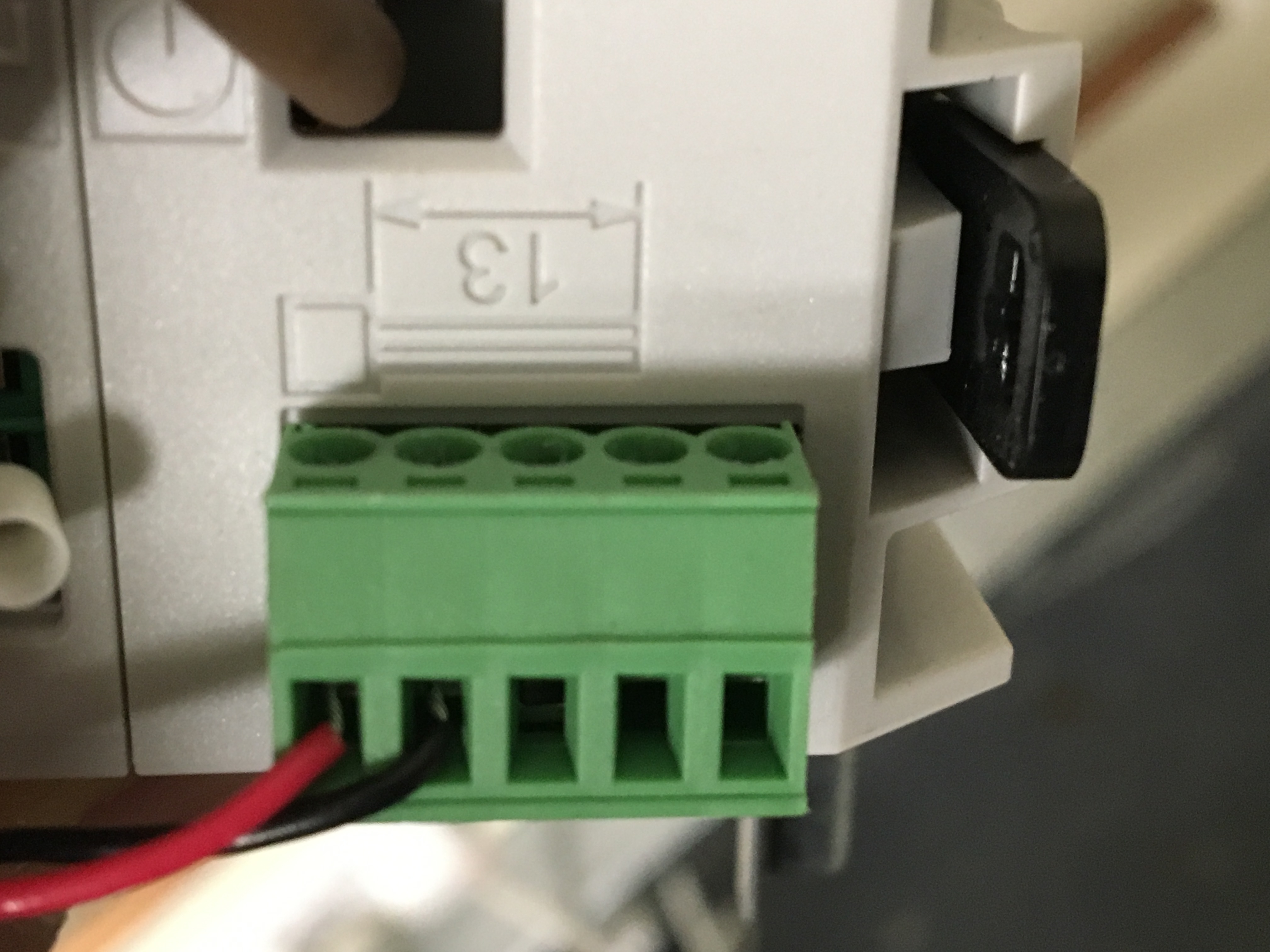
I’ve never handled one of those meters, so this is all conjecture: First, are there no numbers around those terminals, on the ‘bottom’ face in the picture (the top when the stripping length diagram is the right way up)? - is the green part a plug that’s removable, and is there anything underneath?

Here’s where I think you need to look for the parameters to set, and the values. See paragraph 4.1.1:

Set the output PULSE,
set output 1,
set the energy type to active energy exported,
set the frequency to 1800 per kWh [I’m not sure of what defines whether this is pulses per kWh or per MWh!] which should give you one pulse per second @ 2 kW,
set the length to 500, that should give a 1 Hz square wave, more or less,
set the output to Out 1 [Yes, it does look as if you need to tell it this twice! Or maybe what appears to be the second time is actually displaying a confirmation?]

THEN, it looks as if you need to set the I/O, see paragraph 4.1.2:

Select SET,
Select I/O,
Select Pulse Out

It really does read as if you need to set up the pulse to output 1, then set the I/O to accept the pulse output and map it to the physical output. Whether that is actually the case, I don’t know. It is a little contorted. I think you need to assume it’s as written, then if it still doesn’t work, the first thing I’d do is try doing 4.1.2 first, then 4.1.1. Also, keep an eye on the error log to see if the 1004 error goes away (or another one appears).

Farnell’s data sheet says:
Data from B21 can be collected via pulse output or serial
communication. The meter are equipped with a transistor
output for 5-40 VDC external supply. It can be used for pulses
proportionally to the measured energy or various alarms.

So it might be worth swapping the battery polarity. (Why does it appear to conflict with the manual?)