I have what I believe is a typical consumer unit with 32, 16 and 6A trip switches.
I am aware you can buy 5V DIN rail PSU’s but they are not particularly cheap, even from the Far East.
What I believe I need is for 2 or 3 wall sockets to be installed beside the consumer unit but I’m worried it will look rather unsightly. One socket would be for the AC - AC adaptor, one for a 5V PSU to power an ESP and one as a spare if I wanted to power the emonTx / emonTx shield with it’s own supply.
What is the recommended procedure for a neat and tidy system to power the OEM hardware?
I have also been looking at DIN rail mounts for the hardware and at the moment I’m favouring the emonTx shield (with Uno / Leonardo) as my preferred Energy monitoring hardware. I know there are mounts for the emonPi and emonTx but not so much available for the shield system. Does anyone have a 3D printer design for a DIn rail mount for the shield and associated Arduino?
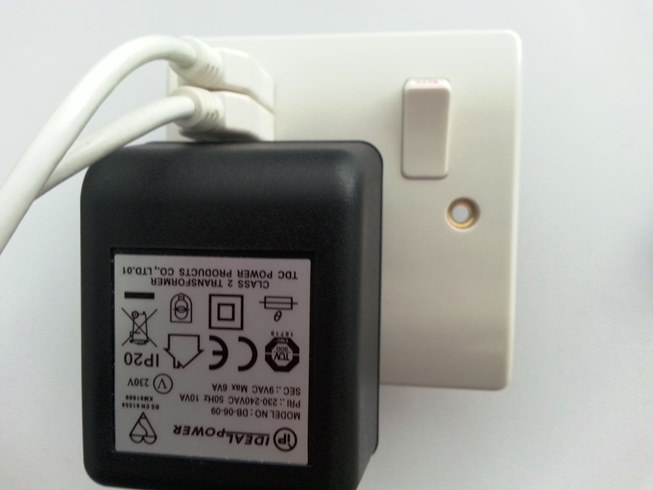
I have a double socket with USB ports next to the CU. At the moment it’s a legacy ethernet-over-powerline one, but I am going to swap this out for a generic MK one soon, not that everything is on wireless
If using a single socket with USB power, just double check there is enough clearance to use the USB ports when using a chunky wall wart, you might just be ok with the OEM shop sold AC:AC I’d think.
But these sockets appear to have the USB ports slightly higher than the LAP one.
and the’re available at B&Q’s too so you could measure one up before you buy.
You could put the whole thing in cheap project enclosure to keep it tidy, plus it reduces the chance of someone unplugging your monitor to charge their phone or plug a hoover in etc. I’ve often used these
which would probably also fit the sheild, arduino and esp8266 along with the socket and wallwart. being plastic it shouldn’t effect the wifi range, just be sure to add some air holes top and bottom as the AC:AC wallwart (and the usb psu) will generate some heat, not alot but it will build up if the box is air tight.
Good point. I am using the OEM AC - AC but I might take it along to the local electrical store tomorrow to check the fit.
I actually have an annoying mains doorbell just above the CU and it has an on / off “light switch” in a 25mm deep enclosure. I say annoying because the doorbell is often mistaken for the communal light switch in our block of apartments and people press it at all times of the day. We also have a video phone wired up to the main entrance so the doorbell is surplus to requirements.
Will try to use this enclosure with dual USB for a tidy job.
I have quite a few project boxes and certainly one that would accommodate the Arduino plus shield but I quite like the appearance of the system without a project box. So ideally I’m looking for a DIN rail mount that will fit directly to the back of a Leonardo / Uno.
I looked up the CT extension docs a week or so back and I will probably do it with some of our secondary energy monitoring systems as the CU is right outside my home office. What I wanted to ask is can you also use shop bought extensions rather than the DIY route?
Read the article several times over recent weeks. Are you saying that nobody supplies correctly shielded extension cables with a female 3.5 mm jack socket at one end, wiring to tip and sleeve (ring NC) and male 3.5mm jack plug at the other end?
Yes, that is exactly what I’m saying. “Correct” in this sense meaning for our specific method of connection. You can’t have read “Can I use a ready-made headphone extension lead?” nor looked carefully enough at the diagram that shows how the plug is wired.
Hint: Look where the cable “screen” would be connected if you use an off-the-shelf lead.
I’m going to wade in here with some anecdotal information that may be helpful. First let me say that I agree with the theory behind the cautions against using commercially wired headphone extensions to extend a CT lead. I’m no expert on such matters, but as an amateur musician, have seen the amount of hum you can get using the wrong cables.
However… I have to confess that I’ve been using cheap (and I mean dirt cheap) eBay 3.5mm audio cables for some time now as primary CT leads. I have a ton of cheap ($2) HWCT-004 solid core CTs installed with anywhere from 1M to 2M leads that are cheap audio cables. They work great. Typically, about 18" of the cable is running down the inside of the electrical panel alongside all of the branch circuit wiring. If there is significant noise, I don’t see it. The accuracy of these cheap solid core CTs blows away the split core units.
So there’s theory and practice. I wouldn’t use a bunch of 3M headphone extensions to place a CT in the next room from the monitor, if nothing else, CT leads originating in a US electric panel are not supposed to be exposed. But I wouldn’t necessarily go through heroics to make an audio quality connection either. Point is, try it and see what happens in your case.
Final point. I read the article that was referenced, and it seems to say that when extending, it doesn’t matter if it’s a voltage or current type CT. That is to say it doesn’t matter if the burden resistor is in the CT or in the measurement device. I haven’t experimented with this, but taking a lesson from measurement standards like 4-20ma output , it seems to me that the current type stands a better chance of negating any resistance in the connecting cord as the CT will (as stated in the article) push the rated current against any reasonable resistance. So the burden in the device will see the rated current, regardless of the resistance of the connection leads. On the other hand, in theory, the voltage produced in the voltage type CT is subject to loss from resistance in the connection leads. The current should be low enough to make those losses negligible for short runs, but when you start talking about longer runs…
I’ve had mixed results with USB power plugs vs USB power supplies in the USA. These devices are primarily intended as charging ports rather than quality dc power supplies. They usually have circuitry to provide higher current on request for charging tablets and phones.
USB power supplies, on the other hand, are all about quality rather than quantity. I’m not saying this won’t work, but you should proceed cautiously.