The way we measure the current is to use the CT you have, but we measure the voltage across the burden resistor (the CT’s load) around 2500 times per second, and compute the rms current that way. Now unless your HomeVision can do that, we need to think of another way.
The HomeVision website isn’t specific, but all the indications are that the analogue inputs expect only slow-moving values like temperatures, so I think it’s fairly certain that you won’t be able to do anything like what we do here. You’ll need to add a full-wave rectifier and smoothing to your CT’s output to obtain the “rectified average” value of the current, and feed that into your controller.
If you’re interested in pursuing that approach, I can look up some details.
[Edit:]
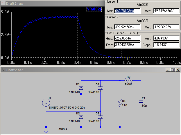
I’ve thrown together a circuit and a quick simulation. I1 is your CT - 0.0707 mA amplitude = 50 mA rms, or 100 A primary current. That feeds a bridge rectifier and the burden resistor (R1) and finally a RC filter removes a large part of the 100 Hz ripple whilst still leaving a reasonably fast response - it reaches the correct output to within 1% in about 260 ms. You can reduce the ripple at the expense of response time. Your 0 - 5 V d.c. output is across C1. Note that this gives the rectified average current, so if you calibrate it with a sine wave, it will be wrong for any other (distorted) wave shape. However, that’s what the majority of budget multimeters will give you.