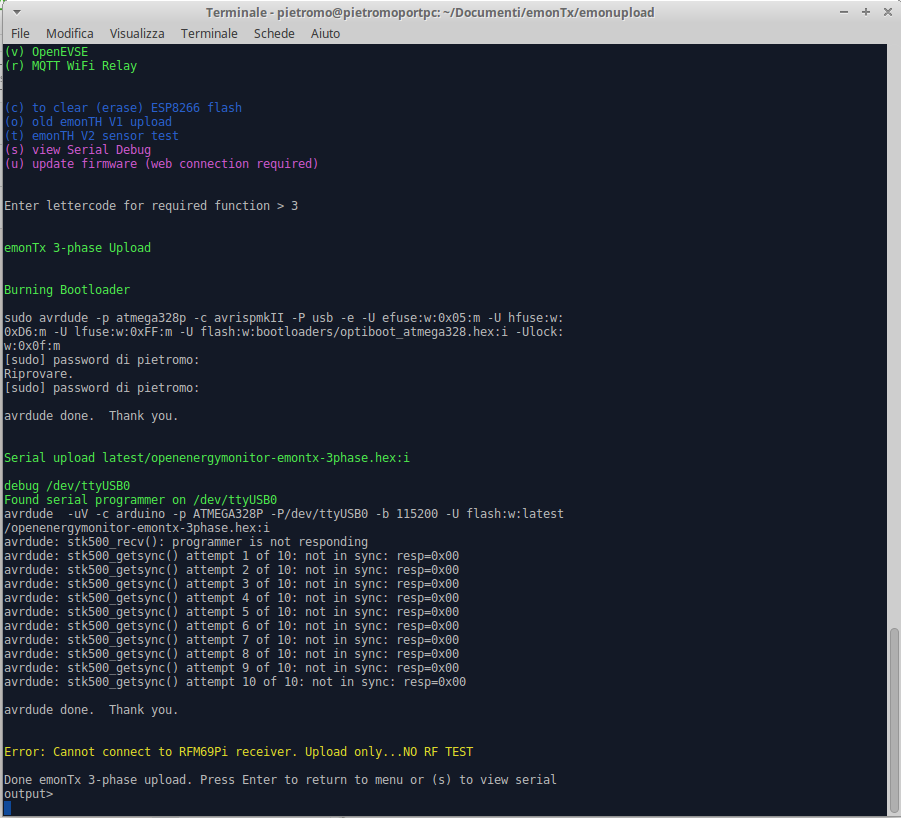
I’ve tried to update the EmonTX FW using the procedure described in this github GitHub - openenergymonitor/emonupload: Upload / update latest OpenEnergyMonitor firmware
But I’ve a problem with the update, see the screen below and tell me with someone can help me.
Thank you
You do not need to burn a new bootloader. I recommend, although this is not the official recommendation, you install the Arduino IDE and libraries as detailed in ‘Learn’. You will in any case need to adjust some values in the 3-phase sketch, then recompile and upload it, so loading the pre-compiled .hex file will not help you.
Hi Robert,
thank you for your help, can you tell me which parameters needs to be changed in the three phase monitor FW, if you have seen this part.
Everything you need to know is in the comments at the beginning of the sketch.
It looks like you’re nearly there with emonupload. If you don’t need to re-compile the FW I would try and avoid it since there is more chance for things to go wrong. If you upload the pre-compiled version using emonupload (or avrdude directly) then you can be 100% sure that you’re running the fully tested FW version.
It looks like emonupload is working ok apart from the programmer not being able to connect to the emonTx. What programmer are you using? Is it connected to the emonTx UART port? If you’re using a non-standard programmer make sure that the pin out matches the programmer we sell in the shop. Also ensure the programmer is supplying 5V to the emonTx, the red LED on the emonTx should light up when you connect the programmer.
@glyn.hudson
Glyn: The ‘discrete’ 3-phase sketch relies critically on phase and timing to get the power in phases 2 & 3 anywhere near correct. Unless the timing is carefully set up for the individual transformers and mains supply frequency as per the instructions in the sketch, accuracy will be compromised.
This is why I suggested that @denni_rostirolla should use the source version of the sketch, so that it can be compiled and adjusted to suit the particular set of hardware in use.
I’ve tried to update the FW with arduino and PlatformIO but the problem remain the same.
I don’t have a programmer, I’ve just connceted a serial USb to the serial connector on the board
http://www.ftdichip.com/Products/Cables/USBTTLSerial.htm
TTL-232RG-VIP-WE.
I’ve connect correctly TX-RX-GND-5V and RTS to the Reset pin. Can you find my error?
The EmonTx is NOT marked according to the standard serial interface convention. Transmitted data appears on the pin labelled “Rx” (i.e. it is looking for Pin Rx), received data should come in on the pin labelled “Tx” (i.e. it is looking for Pin Tx).
Maybe there is a power problem? because I’m powering the board from the mini USB extarnal connector and using the pin of the serial marked as 5V for power the FTDI serial USB converter
I’ve read about this, I’ve tried to exchange the two pins but the problem is still the same
The FTDI web page for your cable says: “Cable features voltage reference input for setting UART signalling levels.”
The emonTx has a 5 V input either via the FTDI connector or the USB connector, but runs on 3.3 V. (5V will destroy the Hope RFM69 CW radio.) Have you set that correctly?
I think, from the way I read the data sheet (Note 8), that the red wire in your cable should be fed from 3.3 V on the emonTx in order to set 3.3 V output levels from the cable.
The USB is at 3.3V, but the board can’t have the sync, I think it could be a bootloader problem but I can’t update it.
That might be the problem, but it is not necessarily that. Those error messages you see simply mean that the programmer cannot communicate with the emonTx. That could be for any number of reasons.
Where are you taking the 3.3 V from?
I think your connections should be:
Red - 3.3 V on the screw connector block (2)
Black - (Gnd) - Gnd on the screw connector block (3) or FTDI GND
Yellow - (Rxd) - FTDI Rx
Orange - (Txd) - FTDI Tx
Green - (RTS) - FTDI RST
Brown - (CTS) - Not used
Can you confirm this is what you have?
Are you able to say if any signal appears of the Orange and Green wires?
I’ve changed the USB to uart cable and now I’m using the TTL-232R-3V3.
Red - not connected
Black - (Gnd) - Gnd on FTDI GND
Yellow - (Rxd) - FTDI Rx
Orange - (Txd) - FTDI Tx
Green - (RTS) - FTDI RST
Brown - (CTS) - Not connected
There are two leds on the usb that blink when there a TX or RX packet, i think the serial is working.
Anyway I think it is less expensive to buy a new board then debugging this problem.