Just wanting to double/triple check that the emonTX can be powered with 5VDC connected to the 5V +ve connection on J6 pin 1 and the ground/5V -ve on J5 pin 3.
I have been powering with a 9VAC plug pack. I am aware that if I wish to keep this as reference voltage I must remove JP2 and power simultaneously with both power sources.
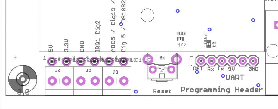
Correct. The connector (it is one block of 6 screw terminals, not 3×2) is clearly labelled on the p.c.b. All the “5 V” places are connected in parallel - the USB connector, the UART and the screw terminals.
It would be a lot easier (for those like me who grew up and learned all this when drawings were drawn by humans with a pen on draughting film) if all the lines joined up in the way I’m used to, instead of having a label and making you do a visual search and then try to remember where all the other lines with the same label are.
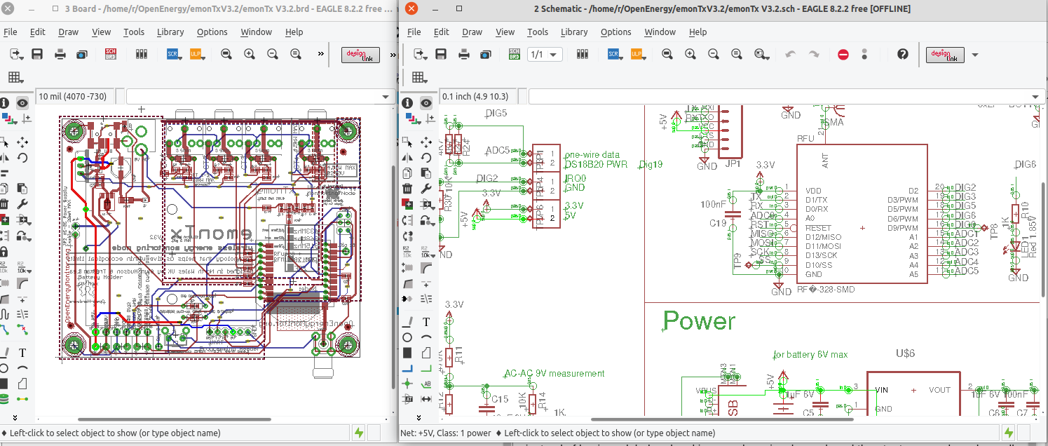
If you download (free) Eagle CAD and open both the layout and schematic, then link the two by clicking the ‘eye’ tool on both, clicking a line or a track usually (if G&T have done it correctly) highlights every point connected on both.
It’s hard to see at this scale, I think I needed to tweak the colours to make it easier: on the p.c.b, the 5 V track is a brighter blue and red, on the schematic it’s a brighter green. Open this link (to the image) in a new browser tab:
It would be fantastic if the board diagram emontx v3.2.brd was available to the public. I have had a good look on the github page and google and it is seemingly unavailable. The diagram I am referring to is the one on the left of your screenshot. Of course the circuit diagram would be very useful for me to have as well. Any chance of providing a link to the files or asking openenergymonitor to upload them to the github page?
Also on another topic, can the current transformers be disconnected from the emonTX for the period of time needed to open the case, attach the 5VDC leads and remove the jumper? 10 minutes or so? From memory I was supplied the YHDC SCT-013 CTs.
I live in Australia where it is illegal to work in AC wiring and I don’t know a friendly sparky - electrician in Australian parlance - who could spend 5 minutes unclipping and reclipping the CT clamps. Had a sparkie here the other day too…
They should be protected by internal zener diodes (or equivalent), but I prefer not to rely on this. If you can isolate the circuits for long enough to unplug the c.t. and short the tip to the sleeve, you can then re-energise, take as long as you like, and everything will be fine. Then isolate again while you remove the short and plug in. A c.t. is always safe when it’s short-circuited.