I’ve now been able to run a test for you. Using an emonTx V2 (because all the input pins are accessible), I’ve linked one of the ADC current inputs to the voltage input, so exactly the same wave is reaching both input pins.
With the phase calibration value set to 0.0, I get a power factor of 0.9877 (to 4 figures).
With the phase calibration value set to 1.0, I get a power factor of 0.9994 (to 4 figures).
p.f. = 0.9877 represents about 9° of phase error, which is close to the number I expect given the sample rate of emonLib.
[Edit: With no input, I see p.f. values anywhere between 0.07 and 0.3, but mostly around 0.13 Those are not of course true power factors, but the result of multiplying random small numbers arising from circuit and power supply noise. ]
I think you must have introduced somewhere, inadvertently of course, either a time delay or a phase shift, into one or both of the measurements. You should not need a phase calibration of -2.0 When I use that, I get a pf of 0.9635, representing a phase/timing error of 15.5° There’s something seriously wrong somewhere.
Have you ensured that the mid-point bias for the ZMPT101 is adequately decoupled, as that will appear as a high-pass filter to the ADC.
The noise source can be the power supply to your Arduino, or it can be the Arduino itself. There’s evidence to suggest that the internal power supply regulator is likely to be better in this respect than most 5 V sources, therefore it’s recommended that you use the 9 - 12 V barrel connector.
You also need to follow or exceed the data sheet recommendations for the ACS712.
[Edit]
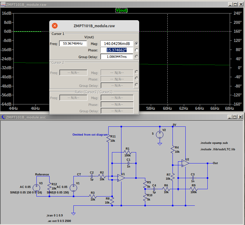
Were you telling the truth when you wrote that you have a ZMPT101B, or were you misleading everybody and do you really have a ZMPT101B MODULE with op.amps. and filters?
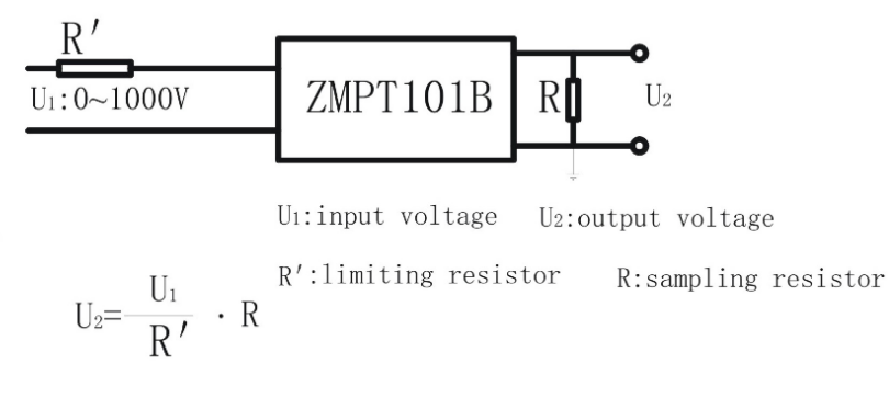
Because if you have, that’s where your 15° phase error is coming from. For our purposes, that module is rubbish - throw it away - just keep the ZPMPT101B itself and follow its data sheet for the voltage multiplier and burden resistors around it, and bias it like an ordinary a.c. adapter according to the instructions in the ‘Learn’ section.