Has anyone ever measured the power factor of their heat pump? Ideally at different compressor speeds. I am assuming the emonHP can measure cos(phi).
I know that for consumers this doesn’t matter, but I am working on some projects that involve a large number of heat pumps that affects grid stability and I just want to make sure im not missing something.
Oddly enough I haven’t been able to find any data or research on this. My expectation is that it will be around 0.95 inductive, due to the compressor operation.
No it can’t, nor can any emonTx or emonPi and they never have been able to, because cos φ is only meaningful in text books where sine waves exist. They usually don’t in the real world.
The definition of power factor is the ratio (real power) / (apparent power), and it’s those two quantities that all OEM software measures and computes power factor.
I’ve not dug out the specific HP software, but my bet is power factor is calculated but never saved or displayed.
How do you define cos φ for a complex wave where each harmonic component will have its own phase shift? Your meter may well be reporting cos φ only for the fundamental, that’s not the same as the overall power factor.
Well, we can calculate it numerically. During continuous operation I expect the heat pump to operate like a linear circuit, hence the current will be sinusoidal.
A first order approximation for some cycle, which is good enough for what I want to test, could be to calculate S = V_rms * I_rms and the average real power P, and then obtain the pf = P/S. This would also work for non-sinusoidal currents, and I expect my ‘smart’ meter to also work this way.
Why? Even if it was a non-inductive resistor with zero temperature coefficient, the current would not necessarily be a true sinusoid because there’s no guarantee that the voltage is. It’s well known that there are harmonics injected into the supply by other consumers, and you can’t ignore those.
If your approximation is ‘good enough’ for your purposes, that’s fine; but in the real world with real waveforms, you can’t without qualification say cos φ is the same as power factor - simply because φ itself doesn’t exist in a meaningful way for a wave containing harmonics.
Which comes back to my assertion: OEM software can calculate power factor and it does so from the definition. It does not calculate cos φ because it cannot - there is no angle φ to measure. What the OEM software cannot do (so far) is show whether the power factor is lagging or leading. For this, a quadrature measurement is needed and there simply hasn’t been enough processing power available for that.
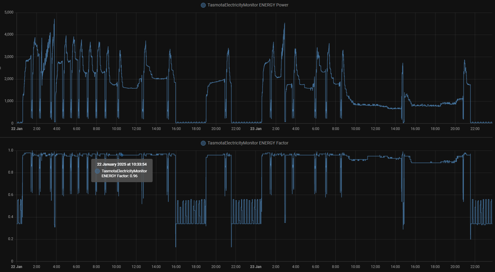
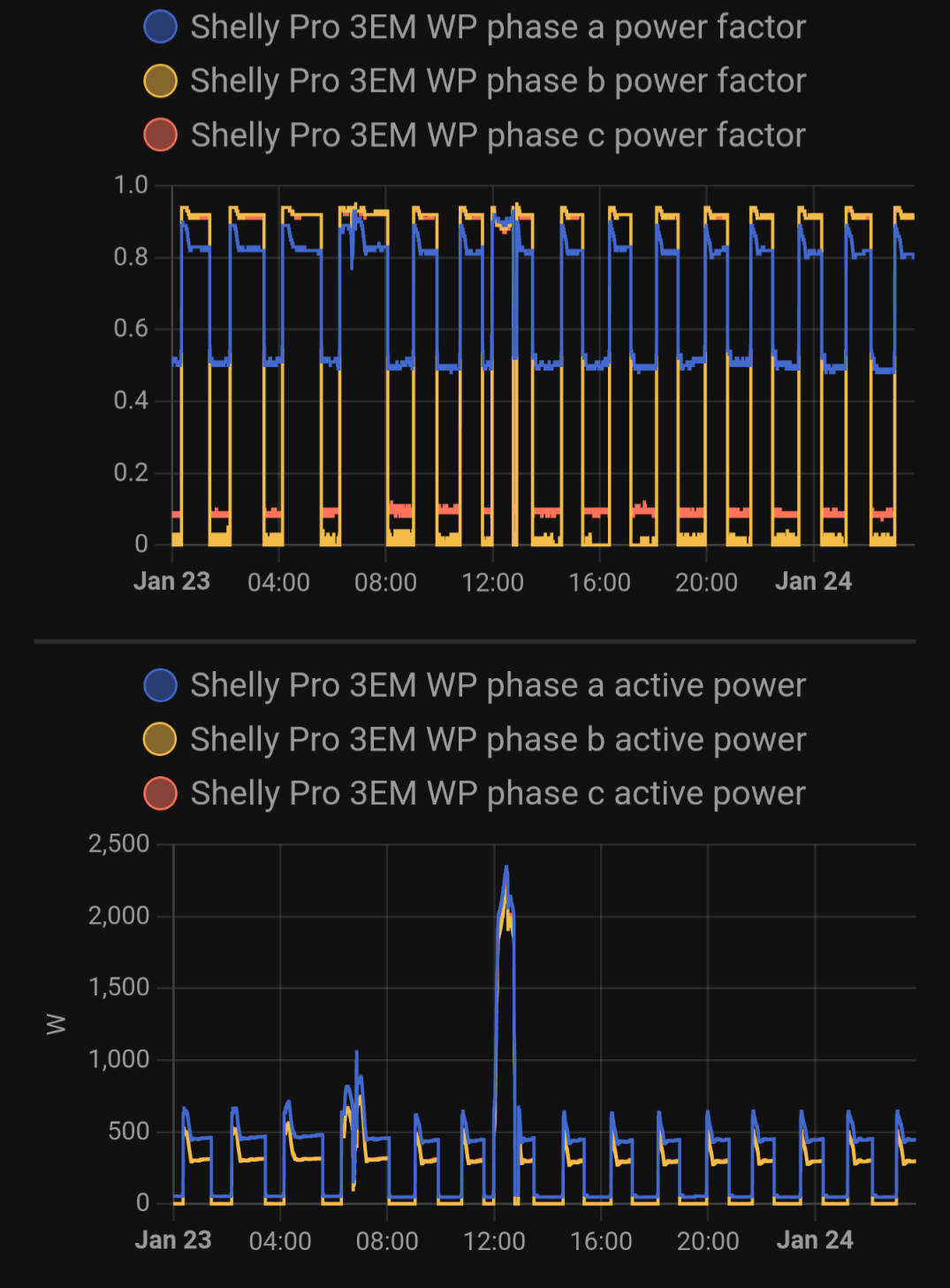
Typically I see a minimum PF of 0.9 at min speed, increasing to 0.95 at higher compressor speed. Phase A also has low load control electronics and the pump, hence the lower PF.
That might be the case, but it would be worth confirming on your heatpump. The first stage of these inverter based devices is to generate DC so they’re basically a power supply from the grid’s point of view, not unlike what’s in your TV, your computer or your EV. What happens after that (inverters, variable speed motors etc.) is not visible to the grid.
The closest thing to a heatpump that I have handy to measure is my inverter based fridge. It’s a long way from the old AC compressor type fridges that cycle on and off all day. In those you might see a fairly sinusoidal lagging current draw typical of an electric motor.
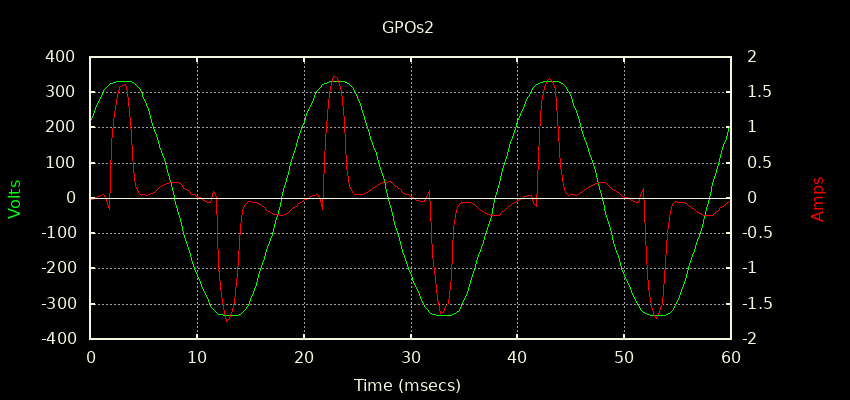
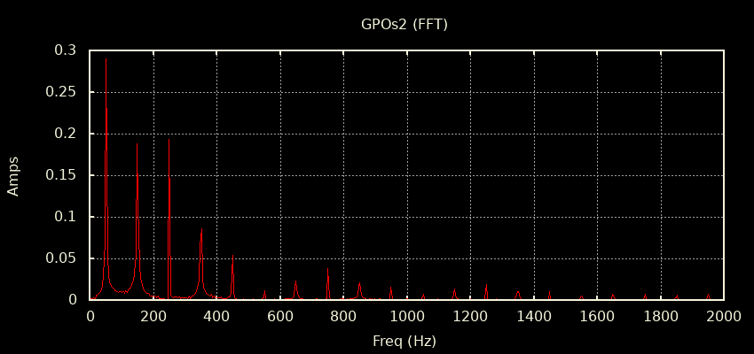
My inverter based fridge is constantly tuning the power going into the compressor to match the current heat load. Once things have reached steady state it hovers around 30 to 40W from memory. I just whacked it up a notch to make it run hard (a fairly constant 100W) and captured a waveview. You can see it’s a long way from sinusoidal but instead shows a classic SMPS signature:
All those harmonics contribute directly to Irms but add almost nothing to RealPower and since
PF = RealPower/(Vrms * Irms) the harmonics make the denominator bigger and do next to nothing to the numerator, resulting in a rather poor PF of 0.63.
If I drill down to look at just the 50 Hz stuff then it appears as a very slightly inductive load:
Solving that triangle will give you a cos(phi) of 0.974 for whatever that’s worth.
So my fridge demonstrates pretty spectacularly just how different PF and cos(phi) are. People often use the terms interchangeably but shouldn’t.
I think the PF of your heatpump will come down to how much effort they’ve put in to designing a PFC supply in the very first stage, where the DC rail is produced. PFC supplies are very common in datacentres and EVs (you can see some examples here). Working in your favour is that your heatpump likely draws a lot more power than the 100W my fridge draws. Generally, the bigger the power supply, the more PFC effort they put in - often by regulation. Those 11kW power supplies in EVs (7.4kW on single phase) do a spectacular job at looking like a resistor to the grid. Your heatpump power supply probably sits somewhere between there my fridge.
Thanks for your input. I did not mean to start a discussion about the definition of cos(phi) vs power factor, I should have used the term power factor.
Heat pumps have high simultaneity, which in some cases is causing voltage to drop below the limit of 207V. This happens mostly in neigborhoods where a lot of heat pumps have been installed and the infrastructure is old.
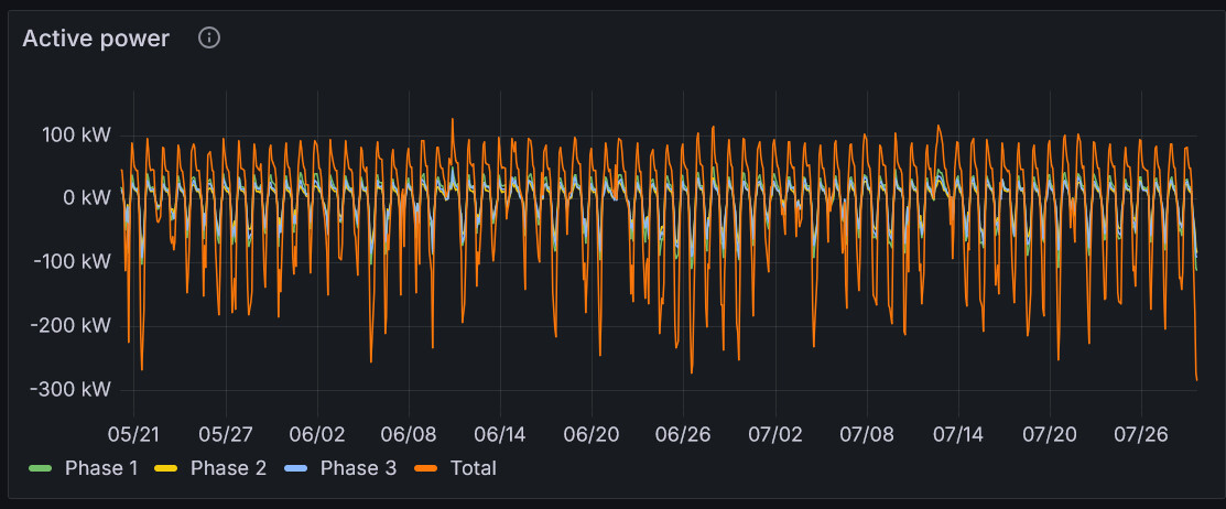
So do PV panels, but in the opposite direction. The good folk of West Devon, where I used to live, had installed so many that on a good summer’s day the mains would nudge 260V. I had to call in Western Power to change the tappings in our local substation.
What a shame that PV and HP effects don’t occur during the same season, so as to cancel one another. Maybe a really big battery…
(PS “Simultaneity” - nice word - so much more interesting than the boring old “concurrence”.)
In the summer, here in Australia, the PV and HP (cooling) effects do tend to cancel each other out. Unfortunately the effect peters out in the late afternoon and early evening.