Power Diversion in NA

I am considering building a power diverter. My current setup is an EmonTX v3 with an EmonBase with 4 CTs. 2 on the line running into my panel (after the solar feed) and 2 on the solar feed. AC voltage wall wart. I also have a grid tie Enphase solar installation. I am not in a net metering state so I essentially give my excess power to the electric company.
Right now I pull data off the emonpi into my Vera and run a scene which controls a zwave switch on a coffee cup heater in a 5 gal water container. Not very elegant or reliable, pretty crude. I would like something better.
Can anyone provide some advice on what I need to make this work? I am been through Robin’s site as well as the wiki, but I still don’t have a full grasp of the parts and connections I need for the US.
Can I use the EmonTX v3 to provide input to one of Robin’s power routers or do I need an additional set of CTs?
The sensing location is not at the dump load location,
Do I need the 3 phase version of the board because I have split phase power?
What steps do I need to take because of split phase power?
Will I need a dump load for each leg when the house load is not balanced?
and probably a lot I have not thought of.

Thanks,
rearden
I think it would be over-complicating things to try to either share the c.t’s or to, in effect, add all of the diverter functionality to the emonTx, or vice-versa. I think the simple route is two more c.t’s.

I would need to check up on that.
Yes you do. There’s a page on Robin’s site that specifically explains this. Or you could contact Robin direct. @calypso_rae here or by email though his website.

You need to know how your meter reacts to various conditions on each leg. If it responds to (charges for) the nett energy across both legs, you don’t need separate dump loads on each leg. But if it treats each leg separately, then you do.

What exactly is the problem? You can extend the c.t. leads, in principal (I think Robin’s kit can’t do this) you can separate the triac switch from the rest, or you can run new power cables to your dump load. Or I think Robin has done a radio link too.

I have (more or less) the same setup he has. i.e. the Enphase microinverters and a split-phase supply.

I used the prototype kit I bought from Robin with a 240 Volt dump load - a 55 Gal drum of water with an immersion heater. I ran it for 9 months and it worked like a champ.

The house is load will rarely if ever be balanced, but a 240 Volt load will be, as it’s connected across both hot legs of the supply, same as his Wh meter.

I don’t want to complicate matters. I also have a Sense. 4 CTs with the Sense and 4 with EmonTx. 8 CTs so far. And 4 more for the power diverter, It is getting a bit crowded in there.

I don’t know how to determine how my bidirectional meter works. All I see from the power company is total power in each direction. I don’t think the cost of separating the loads for each leg would be prohibitive…

My solar interconnect and sensing location is outside the house. The dump load would not be here, Probably 15m or so away.

Bill,
Could you tell me what parts you ordered from Robin and modifications you made? Did you use the SSR? I want to get an overview of the parts, connections and costs for a NA system.

Why did you stop using the device?

The link you posted is giving me an “Oops! That page doesn’t exist or is private.” error.

Thanks!
rearden

No, 2. It only needs to know the nett grid energy.

I think you should be OK with extending the c.t. leads to 15 m, provided that you do it properly, as explained in ‘Learn’.

The last time I tried, I was unable to get access to those wires in a way that I could get a CT around them. I have underground utilities, my solar interconnect is nearly at the meter and outdoors. I will take another look and see what I can do.
I have some space after the interconnect and on the incoming solar.

Which wires are we talking about - the grid connection? Both Robin’s and MartinR’s diverters work by attempting to balance the nett energy flow at the grid connection, i.e. upstream of the infeed from your PV, to zero. They will not work correctly if you cannot obtain the current flowing there. One c.t. (per leg) is obviously the best way, but you could do it with two identical c.t’s, one on the PV infeed and one on the feed to your load centre, and do the subtraction at the point where you connect the c.t. secondaries together.

I think the second is what I will have to use. I have access to the wires from the solar interconnect and access to the wires feeding the house on the house side of the solar interconnect (house usage) but I don’t think I can get access to the wires on the grid side of the solar interconnect which would be grid usage. It is all behind a security lock and/or in conduit. It might be possible to put a CT around the house feed and solar interconnect simultaneously and reverse the direction on the solar wire, but I don’t think there is enough slack in the wire and the CT would be huge,

The diverter itself was one of Robin’s prototypes. Essentially the same hardware he sells now
but with an early version of his firmware. It has a digital display that indicates the amount of energy
diverted, but my need was simply to keep from being charged for energy I was generating.

No mods were made.

Yes. One rated at 90 Amps.

Once my energy supplier installed a net meter, I didn’t need it.

That link was to a discussion Robin, Robert and I had, regarding PV diversion and Wh meters.
I forgot that it’s a PM, so not a shareable link. Sorry 'bout that.

Just for info, that’s from a c.t. inside Robin’s enclosure.

As the diverter was a prototype, i.e. no eclosure, The CT was one I already had.
So all I had to do was connect it to a two pin header on the diverter’s circuit board.

Sounds like Robin has integrated things considerably since I bought the prototype. :+1:

Using proper c.t’s, you wire the secondaries in parallel but with one reversed, and looking at Fig. 5b on the “Use in N.America” page, if the two primary currents are equal, then all the secondary current flows around the loop of the two c.t’s, and none reached the burden. If you have ‘voltage output’ c.t’s, use Fig 5c and the secondary voltages subtract, leaving none going into the diverter.

Could you post pictures of your load center (breaker box) and PV connection?

NA split phase 240/120vac
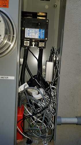
This is a photo of the inside of the connection box which is outside my house.
The power comes from the meter, through the large breaker/switch and into the large cables which then go to my inside breaker panel. 12m+ away as the wire goes.
The medium sized black cables are from my solar interconnect switch which is just outside the photo connected via the conduit on the right.
The thin black wires are to a Type 1 surge protector.
You can see the orange sense with its four white CTs. and the Emon TX with its four black CTs. The antennas are at the bottom and the voltage measure/power for the EmonTx is from a GFCI at the bottom of the solar interconnect (out of frame)
As you can see, I do not have access to place a CT on wires before the solar interconnect. They are integrated into the switch/meter unit. I do have access to the wires feeding the house and the solar interconnect.

If I am interpreting that photo and what you’ve written correctly, coming out of the box with the blue-and-white label are 3 pairs of cables. The thick pair are to your load centre, the medium pair are your PV infeed, and the thin pair are your surge protector. Discounting the surge protector, then there’s only your supplier’s meter upstream of the two terminals I can see on the bottom of that?

If that’s so, you can put a c.t. around the three cables (or just the two thicker ones) and that’s equivalent to a c.t. on the grid connection.

Two things I see right off the bat, need attention in your Main Breaker “can.”

The first one is the PV system feed wires connected to the main breaker.
(the blue and white “box” Robert spoke of earlier)

The problem here is a 200 Amp breaker feeding wires with (at best) a 75 Amp rating,
(and that’s if their jackets are THHN type) which is a major NEC no-no.
(NEC = National Electrical Code) Making matters worse, is the surge supressor wire that’s
connected to one of the SEW lugs. Now you’ve got a wire that’s rated at 20 Amps being protected
by a 200 Amp breaker. That’s a fire looking for a place to start.

It’s always OK to use a wire with a larger ampacity than the breaker, but never the other way around.
e.g. AWG 10 wire (30 Amp max rating) is OK to use on a 20 Amp breaker, but AWG 14 wire
(15 Amp max) would not be OK on a 20 Amp breaker.

I can’t tell for sure, but it looks like your PV feed wires are AWG 6 which,
if they have THHN jackets, are rated at 75 Amps max.
Otherwise, their max rating could be as low as 55 Amps.

The big concern here is an electrical fire. If a fault were to occur on the PV wires, the main breaker would
not likely trip before the wire jackets started burning. Depending on the type of fault, it might not trip at all.
That would not be good.

What you should have is a sub-panel that’s fed from the main breaker with the PV wires backfeeding a
breaker in the sub-panel. As you’re using AWG 6 wire, the sub-panel should have a 50 Amp breaker.

The second thing that’s contrary to the NEC is having low voltage devices i.e. your Sense and
emonTx in the same can as the high voltage wires.

They should be in an enclosure of their own, with only the CT leads running into the high voltage box,
via separate bushings. i.e. not running through the same bushings the HV wires are in now.

Thanks for all the input! I will try to work through the list.

  1. So the fields for the load center wires and the PV infeed will cancel so measured together they will register Import power?

  2. The surge protector is a Type 1. So if I understand the ratings correctly, that means it is designed to not require external overload protection. The fuse is built into the device. “Type 1: Permanently connected, intended for installation between the secondary of the service transformer and the line side of the service disconnect overcurrent device (service equipment).” This is the only high voltage device which I installed, everything else high voltage was installed by an electrician. I installed it after a nearby lighting strike took out a number of devices in my house. I already had multiple Type 2 and Type 3 SPD installed and this adds an additional level to my multi-level defenses.

So even when the SPD is a Type 1, do you believe this install does not follow code?

  1. The PV interconnect (off the photo to the right via the short conduit) contains a switch and 30A fuses. There is an additional switch at the PV panels. If you think this design is still not in compliance, I can disconnect those wires and do a run into the internal load center. This is just the way the commercial electrician wired the PV interconnect.

  2. The wires going to the internal load center, go to another larger breaker and all the individual circuit breakers. (200A panel, I think). I have not seen this design before (not that this means anything), but instead of just having an outside switch, they combined a switch and and additional large circuit breaker before the load center.

  3. The Sense was wired according to their instructions (AFAIK) and I believe that it is internally isolated in a way that the EmonTX is not. I know they did something special to isolate the antenna for use in a high voltage environment and allow it to be placed inside a panel box.

  4. I can get another “can” and put the EmonTx and Sense into them to separate the high and low voltage. That would clean up the current can significantly!.

Thanks for all your advice!
Rearden

1 -

Subtract or add, depending the relative magnitude and direction of the currents. So together you will see the nett current (hence power & energy) flow.

2 - Bill’s point relates not to the surge protector, but to the cable between those terminals and the device itself. He assures me that anything other than the heavy cables to your load centre is not legal there. In the UK, there used to be an exception that allowed for very short cables to be unprotected, provided that there was negligible risk of damage. In my book, to qualify for that, the suppressor would need to be right next to the breaker. I can’t see the surge suppressor, so apart from your rules not allowing that exception, there is a risk of damage.
One further point about that – the more cable resistance and inductance there is (i.e. the longer the wires), the less effective the surge protector will be. If you move the PV to your load centre and connect the surge protector there too, then in this case what resistance there is in those main cables between that breaker and the load centre will actually help the surge suppressor as it will tend to limit the current, but you still need short cables between the surge suppressor and where it connects to your system that it’s trying to protect.

3 -

In view of Bill’s comment, and some private comments he’s made to me, I’d almost suggest you should get the electrician back to do that, at his expense, or he risks losing his job.

Apart from the rules, it’s definitely bad practise to put that jumble of low voltage wiring in the same enclosure and not physically separated from the higher voltage, so moving the Sense and the emonTx out into an adjacent box would be good.

  1. I see your point. The wires into the device are the problem. FWIW, they are the manufacture’s size and length, unchanged. The device starts at the black bushing at the bottom near the Sense. I wanted a device as far upto the line side as possible, and use the impedance of the wire into the Type 2 surge devices in the interior panel to provide a separation between the activity of the two devices. The only other way I know is to have the power company install a Type 1 behind the meter (and pay them $10/mo).

  2. I will look into rewiring the interconnect. The low voltage wiring is my fault and I will get a box for it.