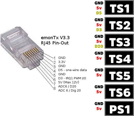
After establishing the pinouts i found out that thers only 3 Digital ports at the RJ45 socket (Digi3, Digi5 and Digi20) so Im still trying to find out how is it possible to plug 7 temp sensors (as shown in emonCMS) even when the EmonTX guide shows up to 4 conencted
btw looks like one of the connections i made went to pulse sensor instead of a temp sensor (since it went from 0 to 1)
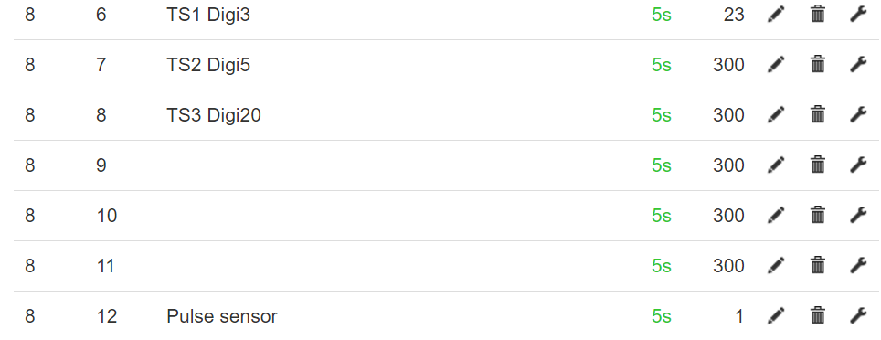
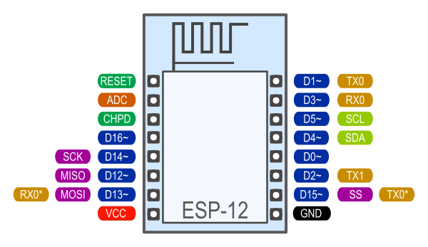
This is my " port map" and im assuming im missing 4 digital ports for 3 Temperature sensors and 1 pulse sensor, after plugging the first 3 TS, only TS1 is showing in emonCMS, also im assuming D20 and Dig20 are the same port
i already know
“300” means the temperature is out of range.
“301” means the sensor has not been detected. That value is loaded at start-up and overwritten when the sensor sends a temperature. So with only one sensor, that’s OK for nos.2-6.
“302” means the sensor has been powered up but not asked to read the temperature, but it has been asked to send the temperature back. It’s likely to mean an intermittent connection.
I might have a dodgy connection (at the momment), however right now would like to know how to make use of all the 7 reserved spaces for temperature using what I currently have (PLUS the pulse sensor)
The only clue I found was from the EmonTX 3.4 guide
Multiple DS18B20s can be daisy-chained, but this will require changes to the pre-installed emonTx firmware itself.
Hi, The temperture sensors are “1-wire” which is a data bus that just uses the one wire for communicating with several devices (up to 128 i think). The way the sensors are connected is to have them all in parrallel (either radial or daisy-chained) so that all the data pins (one per temp sensor) are connected to the one “1-wire” pin on the emonTx.
So D5 (plus power and ground) is the only pin used for temperature sensors regardless of how many there are.
With regard to the number you can connect to any one emonTx, although the 1-wire lib lib allows up to 128 sensors the emonTx is limited to 6 in it’s firmware. This was due to the way the results are transmitted, the standard payload includes 6 temperature results regardless of whether any sensors are fitted, a limit had to be set so that the payload wasn’t too big, that number was 6.
So if you want 7 you will need to edit the standard firmware to accommodate an additional sensor and load that to the emonTx, that will in turn mean the node definition in emonhub.conf will need editing to match your new payload format too.
The single pulse counted is a quirk of the firmware and that first pulse always appears with or without a pulsecounter connected so it is not a result of connecting a temp sensor to it.
If you just wire 6 sensors (all the grounds together, all the lives together and all the data wires together) to the emonTx, you should be able to get 6 results without changing any settings or configuration’s etc, however that 7th one will involve a fair bit more effort.
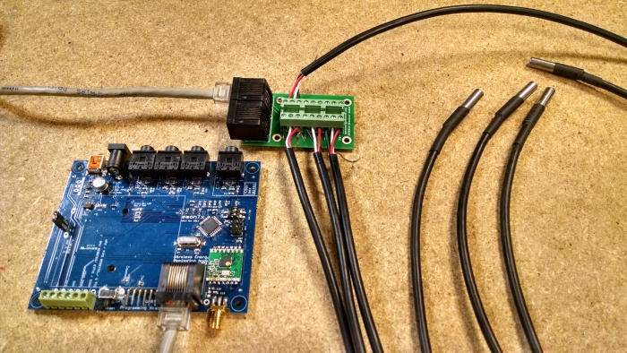
Thanks Paul, got them working right away, Im attemping to plug
5 temp sensors directly to the 3mm headers
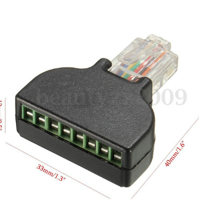
1 pulse sensor on the ethernet RJ45 sensor port
4 Current Transformers
1 Voltage transformer
1 5v 2A DC power supply
if i recall reading glyn wrote in the forums about a hardware limitation to use the 1 pulse sensor along 1 single CT is this still up to date? does it apply to having 5 more temp sensors?
Edit - fixed temp sensor port notation. BT - Moderator
I’m not aware of any limitations beyond those the AC:AC or battery power supplies would impose, running 5 temp sensors and a pulse sensor will make the 5v AC:DC adapter mandatory and then you should have plenty of power. Off-hand I cannot think of any reason why you would be limited to just 1 CT as the CT’s don’t draw any power from the emonTx.
PS -Try to refrain from calling the RJ45 that the sensors are connected to an “Ethernet port”, The connector style is “RJ45” and there are 2 on an emonPi, one of which is an Ethernet port (internet/network) the other RJ45 is for sensors as is the one on the emonTx, Although the same style of connector they are not compatible or interchangeable.
I understand, i just tried the RJ45 sensor port with a pulse sensor a long several temp sensors directly to the PCB with no problems.
This might sound offtopic, but is there a way tu plug an ultrasonic sensor (in adittion to all the ones i have connected) to the board? i tried looking for someone that had done this in order to monitor water levels, but i found odd no cheap solution using the HC-SR04 sensor
Since you are powered from 5v AC:DC you should not need to control the temp sensor power via the RJ45p7 (labelled “ADC6 / D20” in your pic - it is in fact “ADC5 / D19”) so you can edit the firmware to use ADC5/D19 as an input for an additional (ultrasonic?) sensor.
However, where are your water tanks? Ultrasonic level detectors are used quite widely on oil tanks but they can be problematic in water levels. The condensation not only causes failure but whilst it is still working the condensation can cause very erratic readings too. We have water tanks on the North side of our house (sheltered from the sun) and the amount of condensation prevents using ultrasonics, the underside of the tank lids are always dripping in the summer months. There are a few discussions on the old forum that mention ultrasonic level sensors.
Rather than tank, It’s a HUGE cistern I built underground, (totally sheltered from the sun) however i assume and a bit of humidity and condensation will be present nevertheless.
Assuming i do the arrangements to the code, my main doubt that relates to the topic at hand is to see if it could be possible to daisy-chain the Ultrasonic sensor (or any other kind of sensor for the sake of discussion) along the last 2 temp sensors arrays i currently left empty, my logic says yes, but i would think this mostly depends of the datatype of the variable since last time i used sensors of this style the number that measures distance goes from 0 to 1024 depending of the range of the obstacle
I did review a couple of the old water sensors discussions from the old forum but i don’t recall finding a cost effective alternative neither conclusion about how to do it without expending over 100usd+
I’m not sure I understand what you’re trying to do. The temperature sensors send the measurements as a data stream on a OneWire bus, the emonTx being the bus master. Does your ultrasonic sensor also use the one-wire protocol?
I’ve just spotted that buried in your posts above. That sensor cannot be put on the OneWire bus, which you seem to be asking. It also needs two I/O pins, one to send the trigger pulse and one to receive the ‘distance’ pulse. The latter would seem to require an interrupt pin in order to perform the necessary timing with any accuracy, so as the only available interrupt input pin is used for the pulse counter, I think that the only way to use that sensor with your present set-up would be to convert the output pulse into a voltage level to input on ADC 5, and generate the trigger pulse in some other way. There is spare I/O available, but not brought out to terminals.
I currently want to go nuts with the sensors to test the upper limit, but a bunch of questions came up, and i don’t want to overload/kill my emonTX, so Im digging up this thread from the dead to ask, assuming…
Lets assume, I actually wanted to actually daisy chain 100 more temp sensors… dont ask me why
Can the Atmega328p, EmonTX and Emoncms actually handle this kind of array (due to the size of the new array im assuming the package transmitted is going above 7-bit wide address field )?
Has anyone actually tried this with a single Board/uC?
Been reading the 1-wire library is nothing more that the code to daisy chain the sensors to the I2C ports (A4 SDA and A5 SCL), but would simply adding 100 more sensors (expanding the expected RX data type on the emonHub and TX on EmonTX to 100)
Whats the actually tested limit on the MaxTempSensors variable (line 111 EmonTX3)?
Also, assuming i add both the 1 wire library, plug the sensors to GND, D4 and D5 and the lines of code necessary to the new IoTaWatt, and a bunch of sensors (100),
How can i tell the limit of the hardware?
what would the main difference be between the 8bit uC from EmontTX and the 32bit uC from EmonESP in this situation
No, because the length of the message (60 bytes) and the number of sensor nodes (30) permitted by JeeLib restricts you. But if you don’t use JeeLib (say a wired serial connection instead), then those limits won’t apply.
Then you’d likely be limited by the line length/impedance/reflections on the OneWire bus, so you’d probably need a dedicated OneWire buffer to interface between the ATMega328 and the bus.
I’ll leave the remaining questions to somebody who knows more about those aspects than I do.
Robert, I reckon it would be possible. But, you’d have to hold the sensor data in a 6 by x array and send the data across Node 1 first 6, Node 2 second 6 etc. Obviously would mean quite a change to the firmware to achieve this and I wouldn’t fancy the task of wandering round with a hot mug of coffee to dip the sensors in to work out which one is which. In fact it would probably be cold by the time you’d got halfway to the maximum!
Simon
PS I seam to remember reading somewhere that the packet size was kept reasonable to avoid comms issues. Maybe if you only had 1 emonTX and one emonBase then you could extend this?
Then there are the rules about channel occupancy - which I don’t remember off the top of my head. It would as you say need something different to JeeLib. The radio can change the NodeID on the fly without re-starting the RFM, it’s JeeLib that can’t/doesn’t; my r.f. functions in the 3-phase sketch can.
Six sensors is an OEM limit, not a physical one. If there’s nothing else in the data packet, and 2 bytes per sensor, it’s not that many packets. You could go mad and use something like 10 bits per sensor (giving a resolution of 0.1 degrees and a span of 100 degrees, e.g. -40 to + 60) so a 60-byte data packet could in theory carry 48 temperatures. Encoding and decoding would be ‘entertaining’ and definitely non-standard!
Packet size is a problem because it doesn’t use Manchester encoding and if a long string of zeros is sent, the receiver can loose synchronism and the packet fails. If you can guarantee not sending a long string of zeros (like 6 unused sensors initialised to zero), it’s not a problem.
Even when that’s overcome, it still leaves interfacing the bus to be solved, because I think 100 sensors is asking for a proper matched bus interface to minimise reflections.
I don’t think your coffee is at risk, you’d have to test each sensor individually and hard-code the addresses, because if you use the ‘search’ routine and one goes missing, they all shuffle down a slot so your mapping in emoncms becomes wrong.