We want to increase the spread of emontx in Germany. For this we are optimizing the 3phase firmware so that it works plug & play on a three-phase connection in Germany (no firmware modifications necessary), with three current sensors and one EU-plug. We will also send ready-configured emontx directly from Germany (we have already bought units from Megni).
For this we would like to create better default values and send a pull request for that. The best calibration values which we have determined so far are quite different from the current default values.
These are our current values:
Calibration constant for voltage input: double Vcal = 249.5;
Can someone confirm the values or contribute their own/better values?
We are still unsure how to best integrate the calibration values for the EU-plug. The UK and USA voltage calbration can already be changed with one of the DIP switches. But how to add a third calibration value?
One last thing we would like to change: Now the second DIP-switch reduces the NodeID, but reducing from the default (11) means 10 and that doesn`t match the correct emonhub template. So it should actually increase the NodeID to 12. Are you ok with that?
I don’t believe that you can successfully and accurately operate the 3-phase sketch without individually calibrating at the voltage at the individual location, because the phase errors on the 2nd & 3rd phases are critically dependent of the phase error of the a.c. adapter, and that depends strongly on the system voltage. This phase error is less significant on the 1st phase because the change of the cosine value around zero is very small, whereas around 120° it is much larger. Therefore, a small change in the phase error of the v.t. looks like a very much larger phase error in phases 2 & 3.
As I have always said, and it is written in the comments in the sketch, that method (of delaying the 1st phase voltage in order to calculate real power in the 2nd & 3rd phases) is an approximation. It is absolutely necessary that the user knows and accepts that.
I suggested some time ago that 3-phase emonTx should be developed in order to satisfy the market that you are addressing, but that suggestion has yet to be taken up.
@glyn.hudson
I cannot be supportive of the proposal that a ‘plug-and-play’ 3-phase sketch is practical.
Hi Robert, thank you for your Feedback, always much appreciated!
Yes good point with the calibration beeing dependent of the voltage level. So we need calibration values for each of the three voltage transformers.
I don’t think it’s necessary to calibrate each device. I have a lot running at differend locations in Germany and I have to say I’m quite impressed about the accuracy with only one voltage measurement (so nice work Robert!). Only the third phase is not perfect, will try to improve that. Just a thought: if the error increases with the angle, would it be possible to subtract 120 degree instead of adding 240 for the third phase?
With developing a three phase emontx do you mean one with 3 voltage Inputs? We developed that but it’s really not handy, as you need 3 sockets for the three voltage transformer. Thats why I like this approach more.
Erm… That means you need to predict what the phase 1 voltage will be 6.66 ms before it happens! (I think you need to look again at exactly how the sketch works.)
The errors (or more likely, lack of stability) will be down to the longer delay experienced by the voltage wave (determined by the emonTx’s processing speed) compared against the variable (±1%) mains frequency. So a slight shift of frequency by either will have twice the effect on phase 3 as it does on phase 2.
When time permits, I fully intend to expand MartinR’s phase-locked loop to 3 phases. This should eliminate that last error, leaving only voltage variations as a source of uncertainty.
I understand: trying to predict the future will probably not make it more accurate
It looks indeed like a “lack of stability”. The values of the third phase are jumping: sometimes it’s quite accurate on the third phase sometimes not.
That sound’s great so I will continue testing with the PLL approach.
I am sorry, I have expressed myself badly. I don’t have the knowledge to improve this kind of firmware. But you did send me your current PLL state one year ago and if that is the solution for a more accurate three phase approach then I will continue using (and so testing) this one.
I hope it is now better to understand. My english is not as good as your german
Ah, I understand now.
There are, basically, three ways to measure (say) a voltage:
The ‘simple and obvious’ way. This is how emonLib works. It samples for a period of time, stops, calculates the result and sends it.
The ‘continuous’ way. This runs the ADC separately from the main program (hence a lot faster), and the ADC interrupts the main program to process and pass to it the raw values. Robin’s diverter works like this.
The ‘PLL’ way. This locks the sample rate to the mains, so unlike methods 1 & 2, the samples are taken at the same point on the wave for each cycle. For a three-phase system, if the number of samples is a fixed multiple of three, then all the variables associated with timing for phases 2 & 3 become constants, and a major difficulty goes away. However, you’ve still got the difficulty of the phase errors in the transformers, but it’s no worse than for a single phase.
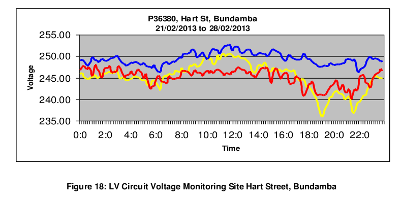
Out of interest, do you have any data on how well balanced the LV phases are in Germany? Here in SEQ the voltages vary a lot from phase to phase. I’ve also seen differences of ~10V between phases in central Auckland.
Voltage balance is my main worry when you know only one phase and must hope the other two track it. But without 3 sockets and the attendant worry of the increased risk and attendant danger from a line-line shock, there’s little that can be done (without developing and calibrating a non-invasive capacitive voltage probe - see the ‘Archived’ forum for details and comments).
It is at the user’s discretion whether to take the easy route and hope that the accuracy is ‘good enough’, or to add the complication and cost of measuring the three phases properly.
Yes, I’m more interested in whether or not Germany has somehow cracked that imbalance problem. I think here it is exacerbated by a lot of single phase houses with single phase PV systems and probably not a lot of thought into balancing them across phases. If Germany mandates (for instance) that all PV installs on 3-phase houses must be 3-phase inverters it might improve things, or maybe the voltage variations in Germany are just like they are here.
I know in the UK, houses are, or used to be, connected R - Y - B - B - Y - R, but not necessarily starting at the beginning of the sequence for each street, in an attempt to keep an overall balance. I found two marker discs near my intake, and when I carefully scraped the paint off that was courtesy of the previous owner, I found one was black (neutral) and the other white (phase - before it became yellow, before it became grey ).
I presume it could depend on the size of the final distribution transformer, hence the number of consumers served.
Thanks Robert for the detailed overview about the different methods and their advantages and disadvantages. So the PLL would obviously improve it.
I could sample all three voltages for a period. But unfortunatly I can’t extrapolate the results to whole Germany as the voltage can be quite different locally. It’s not like the frequency which is the same in the Continental Synchronous Area. Maybe I can find some studies or other publishing about that.
But you are right with the PV installations: you are not allowed to connect more than 4,6 kWp to only one phase.
That’s also the case here, and why it’s hard - with the a.c. adapter whose phase error is quite so voltage-dependent - to say that ‘plug-&-play’ will be successful.
IMHO individually calibration can not really solve the problem of fluctuating voltage. Because the voltage (at least in Germany) changes during day and night times. For example during night times my voltage is about 240 V and during day times around 230 V or less.
But as the phase shift is dependent of the voltage and the voltage is measured by the emontx shouldn’t it be possible to compensate it?
It should be, but as far as I know, nobody has attempted it. What you can do is re-order the maths in emonLib (which I’ve done and put forward a few days ago for review by the staff), and then it’s possible to apply PHASECAL retrospectively to the samples you have just measured. If you want to apply voltage correction, at that point you have the rms voltage, so even a straight line would be a reasonable approximation. You would probably wish to do the same for the current transformers, though the variation of phase error against current is far smaller with those.
But you do need to take some euro a.c. adapters and measure the phase error in order to obtain a representative correction that you can confidently apply universally. There’s no guarantee that it will be the same as the UK ones that I have measured.
Here is a follow up: @Robert.Wall was so kind to improve the 3-phase firmware this way. With this new firmware the plug&play approach is much more realistic as before. The key improvements are:
Continuous monitoring of one voltage channel and up to 4 current channels.
Gives an accurate measure of rapidly varying loads.
It locks the sample rate of the measurement to the mains frequency. This way the measurement will be done at exactly the same place on the wave (as far as I understood the magic
The greatest advantage: individually calibration to obtain the correct values for phascal1-3 is not longer necessary! No more complicated calibration procedure and this issue is completely solved.
One side effect: the emonTx is now also measuring the frequency, which is working quite well. I compared emonTx at different locations and they all show the same frequency and it also fit’s with: Timeline of the utility frequency: Timeline
many other improvements, like a config menu …
I’m testing this firmware now since some weeks and I’m really happy with it. @glyn.hudson I suggest to replace the old 3-phase firmware with the much improved one, so that everyone can benefit of it.

 ).
).